
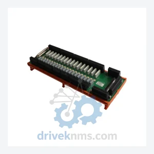
Robicon A5E01649374 Control Module – Obsolete Perfect Harmony Series Spare Part
Robicon A5E01649374 is listed for Harmony RFQ review. Confirm quantity, condition and destination before quotation.
RFQ-ready industrial model
Model: A5E01708486
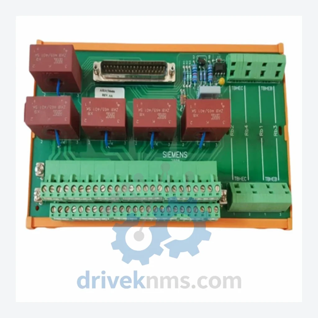
Product Overview
Commercial availability is handled through direct RFQ, model verification and export-oriented follow-up rather than public cart checkout.
Datasheet Preview
Use attached product manuals when available. If the manual is not public yet, request the full file directly through RFQ.
Commercial Path
Product pages on DRIVEKNMS are designed to verify model, brand and series first, then move the buyer into one clean quotation path.
Technical Dossier
RFQ support for obsolete parts: Send the model number, required quantity and destination so DriveKNMS can confirm sourcing options before quotation.
| Parameter | Detail |
|---|---|
| Part Number | A5E01708486 |
| Manufacturer | Robicon (Siemens legacy brand) |
| Series | Perfect Harmony MV Drive |
| Component Type | Signal Control Board |
| Discontinuation Status | Discontinued / Obsolete – No longer in OEM production |
| Country of Origin | United States |
| Compatible Systems | Robicon Perfect Harmony Series (GH150, GH180, N Series) |
| Typical Application | Medium Voltage Variable Frequency Drive signal processing and control interface |
Note: Electrical parameters not independently verified. Specifications above are based on known platform data. DriveKNMS does not publish unverified electrical values. Contact us for datasheet support.
The Robicon Perfect Harmony platform was one of the most widely deployed medium voltage drive architectures in heavy industry — cement, mining, oil & gas, water treatment, and power generation. Thousands of units remain in active service globally, yet Robicon's original manufacturing lines have long since been absorbed and discontinued under Siemens' portfolio restructuring.
The A5E01708486 signal control board sits at the core of the drive's communication and control architecture. It manages the interface between the operator control layer and the power cell modules. Without a functioning board, the drive cannot execute speed commands, cannot respond to fault signals, and cannot protect downstream equipment. There is no field-repairable workaround. The board must be replaced with the correct part.
For plant managers facing system retirement pressure, the calculus is straightforward: a verified spare board at a fraction of a percent of system replacement cost buys 5 to 10 additional years of reliable operation. Facilities that have maintained a strategic inventory of critical signal and control boards have consistently deferred multi-million dollar capital projects — not through luck, but through deliberate asset protection planning.
The alternative — waiting until failure occurs and then scrambling for a part that has been out of production for years — is the scenario that forces emergency shutdowns, expedited freight costs, and ultimately, unplanned capital expenditure under the worst possible conditions.
Every A5E01708486 unit processed by DriveKNMS passes a structured 5-step quality protocol before it is offered for sale:
Units are packaged in anti-static bags with foam cushioning and shipped with full traceability documentation.
Q: How do I know the unit is genuine and not a counterfeit?
A: All units are sourced through verified industrial channels. Physical markings, board revision codes, and component layouts are cross-referenced against known authentic examples. We do not source from unverified secondary markets.
Q: Can this board be used across different Perfect Harmony variants?
A: Compatibility depends on the specific drive series and revision. Contact DriveKNMS with your drive nameplate data and we will confirm compatibility before dispatch review.
Continue The Model Path
Move from this exact model into the matching system hub, brand archive, model-family archive or lifecycle sourcing route before sending a final RFQ list.
Related Paths
Robicon A5E01649374 is listed for Harmony RFQ review. Confirm quantity, condition and destination before quotation.
Robicon A1A460A68.23M/460A68.10 is listed for Harmony RFQ review. Confirm quantity, condition and destination before quotation.
Robicon A1A283739.00 is listed for Harmony RFQ review. Confirm quantity, condition and destination before quotation.