
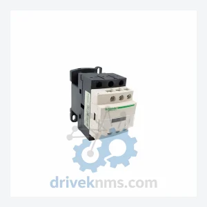
Schneider Electric LC1D12M7C AC Contactor – TeSys D Series
Schneider Electric LC1D12M7C is listed for TeSys D RFQ review. Confirm quantity, condition and destination before quotation.
RFQ-ready industrial model
Model: EOCR-SS EOCRSS-05RY7
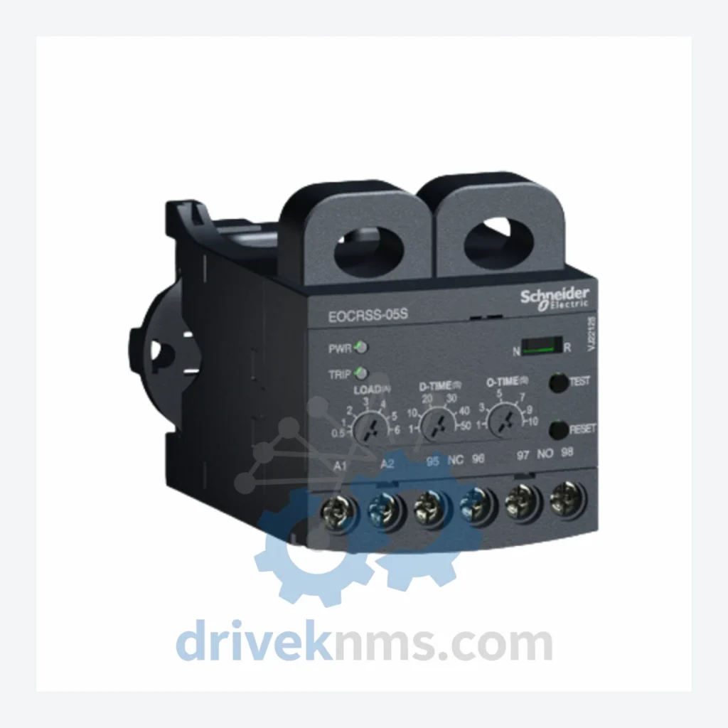
Product Overview
Commercial availability is handled through direct RFQ, model verification and export-oriented follow-up rather than public cart checkout.
Datasheet Preview
Use attached product manuals when available. If the manual is not public yet, request the full file directly through RFQ.
Commercial Path
Product pages on DRIVEKNMS are designed to verify model, brand and series first, then move the buyer into one clean quotation path.
Technical Dossier
The EOCR-SS lineage originates from Samwha Electric's early solid-state relay development in South Korea during the late 1980s. The first-generation EOCR-SS units used discrete analog circuitry for current sensing, with fixed trip-class settings and limited adjustment range (typically 0.5–5 A or 3–30 A bands). These units were widely adopted in Asian heavy industry through the 1990s due to their low cost and robust construction relative to European alternatives.
The second generation, introduced in the mid-1990s, added phase-sequence detection and improved EMI immunity, addressing field failures in variable-frequency drive (VFD) environments. The suffix structure was standardized during this period: the numeric segment (e.g., 05, 1, 2, 5) denotes the maximum current range in amperes, while suffix letters encode output relay configuration (R = relay output), reset mode (Y = manual/auto selectable), and auxiliary contact count (7 = specific contact arrangement).
Following Schneider Electric's acquisition of the SE-Relays product line, the EOCR-SS series was integrated into the TeSys ecosystem documentation but retained its original part numbering for backward compatibility. Current production units are functionally equivalent to legacy variants but may differ in terminal block design and label language. Users migrating from legacy EOCR-SS to modern TeSys D or TeSys Deca overload relays must verify coil voltage, trip-class range, and auxiliary contact configuration before substitution, as direct pin-for-pin replacement is not guaranteed across all frame sizes.
The following SKUs represent the documented EOCR-SS production range. Each unit is a self-contained electronic overload relay with integrated current transformer sensing. Classification follows functional current range and output configuration.
Standard Current Range — Relay Output, Manual/Auto Reset:
Extended Range — With Ground Fault Detection:
Variants with Phase-Loss & Sequence Protection:
EOCR-SS units present specific testing challenges due to their solid-state sensing circuitry and relay output stage. DriveKNMS applies the following test protocol to all EOCR-SS inventory prior to dispatch:
Continue The Model Path
Move from this exact model into the matching system hub, brand archive, model-family archive or lifecycle sourcing route before sending a final RFQ list.
Related Paths
Schneider Electric LC1D12M7C is listed for TeSys D RFQ review. Confirm quantity, condition and destination before quotation.
Schneider Electric 140CRP93100 is listed for Modicon Quantum RFQ review. Confirm quantity, condition and destination before quotation.
Schneider Electric 140CHS11000 is listed for Quantum Series RFQ review. Confirm quantity, condition and destination before quotation.