
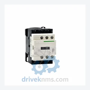
Schneider Electric TeSys D Series Contactors: LC1D09M7C
Schneider Electric LC1D09M7C is listed for TeSys D RFQ review. Confirm quantity, condition and destination before quotation.
RFQ-ready industrial model
Model: LC1D620M7C
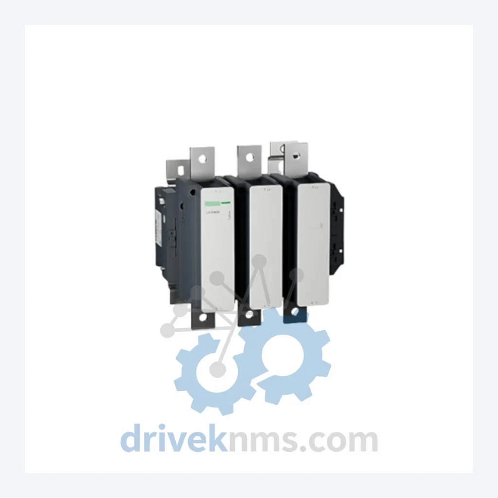
Product Overview
Commercial availability is handled through direct RFQ, model verification and export-oriented follow-up rather than public cart checkout.
Datasheet Preview
Use attached product manuals when available. If the manual is not public yet, request the full file directly through RFQ.
Commercial Path
Product pages on DRIVEKNMS are designed to verify model, brand and series first, then move the buyer into one clean quotation path.
Technical Dossier
DriveKNMS reviews sourcing options for this model through RFQ handling before quotation.
| Manufacturer | Schneider Electric |
| Part Number / SKU | LC1D620M7C |
| Series | TeSys D |
| Type | 3-Pole AC Magnetic Contactor |
| Rated Current (AC-3) | 620 A |
| Coil Voltage | 220 V AC, 50/60 Hz (M7 designation) |
| Auxiliary Contacts | 1 NO + 1 NC (integrated) |
| Mounting | DIN rail / panel mount |
| Standards | IEC 60947-4-1, EN 60947-4-1 |
| Country of Origin | France |
| Product Status | Active / Mature – Critical Emergency Spare |
The LC1D620M7C operates at the high end of the TeSys D current range. Contactors at this rating are typically installed in motor control centers (MCCs) driving large pumps, compressors, fans, and conveyor drives. The failure mode of a contactor at this scale is rarely gradual — coil burnout, contact welding, or arc chute degradation can cause immediate and complete loss of motor control with no warning.
Every LC1D620M7C unit shipped by DriveKNMS passes a structured 5-step pre-shipment inspection protocol:
Q: What is the recommended spare parts holding strategy for this contactor?
A: For non-redundant critical motor circuits, maintain one spare per installed unit. For facilities with multiple LC1D620M7C installations, a pooled spare ratio of 1:3 to 1:5 is standard industry practice, adjusted based on operating hours and process criticality.
Continue The Model Path
Move from this exact model into the matching system hub, brand archive, model-family archive or lifecycle sourcing route before sending a final RFQ list.
Related Paths
Schneider Electric LC1D09M7C is listed for TeSys D RFQ review. Confirm quantity, condition and destination before quotation.
Schneider Electric LC1D38M7C is listed for TeSys D RFQ review. Confirm quantity, condition and destination before quotation.
Schneider Electric LC1D32M7C is listed for TeSys D RFQ review. Confirm quantity, condition and destination before quotation.