
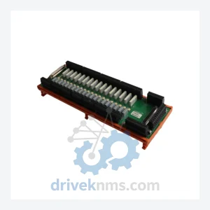
Robicon A5E01649374 Control Module – Obsolete Perfect Harmony Series Spare Part
Robicon A5E01649374 is listed for Harmony RFQ review. Confirm quantity, condition and destination before quotation.
RFQ-ready industrial model
Model: ROBICON F7E1A6G2 A1A0100275
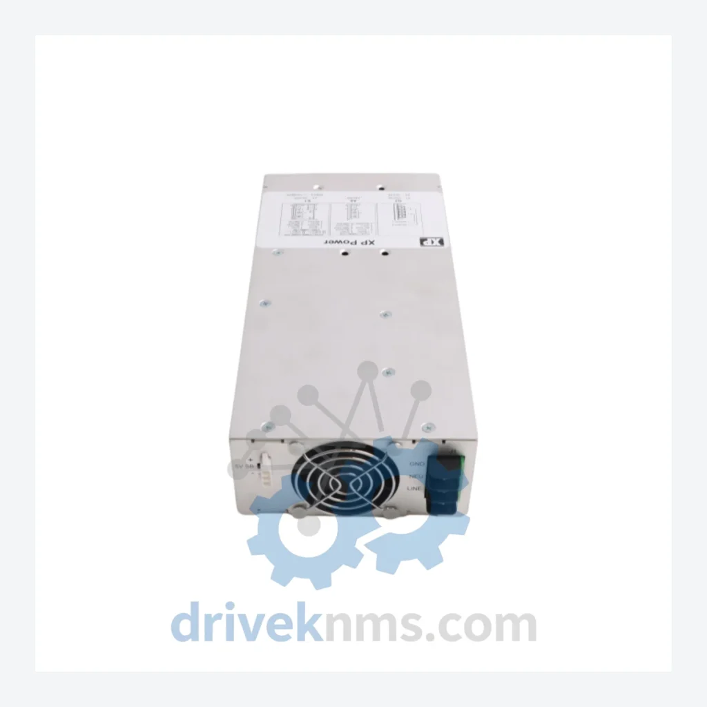
Product Overview
Commercial availability is handled through direct RFQ, model verification and export-oriented follow-up rather than public cart checkout.
Datasheet Preview
Use attached product manuals when available. If the manual is not public yet, request the full file directly through RFQ.
Commercial Path
Product pages on DRIVEKNMS are designed to verify model, brand and series first, then move the buyer into one clean quotation path.
Technical Dossier
The Siemens ROBICON Perfect Harmony series is a medium-voltage variable frequency drive (VFD) platform engineered for continuous-duty, high-power industrial applications. Deployed across petrochemical refineries, nuclear power auxiliary systems, offshore platforms, LNG compression trains, and large-scale water treatment infrastructure, the Perfect Harmony architecture operates in the 2.3 kV to 13.8 kV range and covers power ratings from 150 kW to beyond 30 MW. Its cell-based, cascaded H-bridge topology eliminates the need for input transformers in many configurations and produces near-sinusoidal output waveforms, making it the reference design for retrofit and greenfield projects where harmonic distortion limits are contractually enforced. The ROBICON F7E1A6G2 A1A0100275 is a power module assembly within this platform, serving as a replaceable power cell unit responsible for voltage synthesis within the drive's multi-cell output stage.
The ROBICON brand originated with Robicon Corporation, Pittsburgh, PA, whose cascaded H-bridge drive topology was patented in the early 1990s and commercialized as the Perfect Harmony series. Siemens AG acquired Robicon in 2005, integrating the product line into its Large Drives Applications (LDA) division under the designation SINAMICS Perfect Harmony GH180 for new production, while legacy ROBICON-branded hardware continued to be supported under the original part numbering schema.
The architectural evolution spans three identifiable generations. The first generation (pre-2000) used discrete IGBT gate driver boards with analog feedback loops and proprietary fiber-optic communication between the cell controller and the central control board. Compatibility between generations is limited: first-generation cell boards are not electrically interchangeable with second-generation assemblies without modification to the fiber-optic interface protocol. The second generation (2000–2010) introduced DSP-based cell controllers, improved fault diagnostics, and standardized the A1A01xxxxx part number schema for power cell assemblies, of which the A1A0100275 is a member. The third generation, represented by the GH180 and GH150 product lines, uses a unified SINAMICS control platform with Profibus/Profinet integration and is backward-compatible at the mechanical mounting level in some frame sizes but requires control board substitution. Operators maintaining legacy ROBICON installations must source original-schema parts to avoid control firmware incompatibility.
The following SKUs represent verified, commonly stocked components within the ROBICON Perfect Harmony platform. Each entry identifies the module's functional role within the drive system.
Power Cell / Power Module Assemblies
Cell Controller / Gate Driver Boards
Central Control Boards
Power Supply Modules
Communication & I/O Modules
Siemens formally transitioned new drive production to the SINAMICS GH180 platform following the 2005 acquisition, placing the original ROBICON part number schema into a managed obsolescence lifecycle. As of 2026, the majority of A1A01xxxxx series components are no longer available through standard Siemens distribution channels and must be sourced from specialist industrial spare parts suppliers.
Power cell assemblies such as the A1A0100275 undergo a multi-stage verification protocol before dispatch. Each unit is subjected to dielectric withstand testing at 2× rated DC bus voltage to confirm IGBT and capacitor bank integrity. Gate driver signal integrity is verified under load simulation using a resistive dummy load, confirming switching waveform rise time and dead-band timing against OEM specification. Fiber-optic transceiver output power is measured and compared against the receiver sensitivity threshold of the target cell controller board to confirm link margin. For cell controller and MCB boards, firmware version is read and documented; boards carrying non-current firmware revisions are flagged and the customer is advised prior to shipment. All units are burned in for a minimum of 4 hours at rated thermal load before final inspection and packaging.
Continue The Model Path
Move from this exact model into the matching system hub, brand archive, model-family archive or lifecycle sourcing route before sending a final RFQ list.
Related Paths
Robicon A5E01649374 is listed for Harmony RFQ review. Confirm quantity, condition and destination before quotation.
Robicon A1A460A68.23M/460A68.10 is listed for Harmony RFQ review. Confirm quantity, condition and destination before quotation.
Robicon A5E01708486 is listed for Harmony RFQ review. Confirm quantity, condition and destination before quotation.