
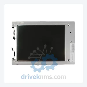
TOSHIBA LTM Series LCD Display Modules LTM09C016K
Toshiba LTM09C016K is listed for LTM Series LCD Display RFQ review. Confirm quantity, condition and destination before quotation.
RFQ-ready industrial model
Model: B200P16DOP-1
Product Overview
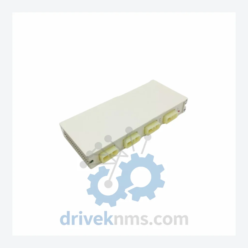
Commercial availability is handled through direct RFQ, model verification and export-oriented follow-up rather than public cart checkout.
Datasheet Preview
Use attached product manuals when available. If the manual is not public yet, request the full file directly through RFQ.
Commercial Path
Product pages on DRIVEKNMS are designed to verify model, brand and series first, then move the buyer into one clean quotation path.
Technical Dossier
The B200 platform was introduced as part of Toshiba's programmable controller expansion into mid-scale industrial automation, succeeding earlier T-series rack systems. The architecture is built around a parallel backplane bus with fixed slot addressing, supporting a base rack and expansion racks connected via dedicated I/O bus cables. CPU modules communicate with I/O modules through a synchronous scan protocol, with typical scan times in the 1–10 ms range depending on program size and I/O count.
Early B200 configurations used discrete transistor-output and relay-output modules with 8- or 16-point density. Later revisions introduced higher-density 32-point modules and analog I/O cards with 12-bit and 14-bit resolution. Communication options expanded over the product lifecycle to include RS-232C, RS-485, and proprietary Toshiba network adapters for integration with SCADA and DCS supervisory layers.
Compatibility constraints are a known engineering consideration: B200 CPU firmware versions are tied to specific module hardware revisions. Substituting a module from a different production batch without verifying firmware compatibility can result in initialization faults or degraded I/O response. DriveKNMS maintains hardware revision records for all stocked B200 modules to support compatibility-verified replacements.
CPU & Controller Modules
DC Output Modules
DC Input Modules
AC Output Modules
AC Input Modules
Analog I/O Modules
Communication & Power Modules
Cross-reference support is available for customers evaluating migration from B200 to current Toshiba or third-party PLC platforms, including I/O point mapping, rack layout analysis, and program conversion feasibility assessment.
B200 modules use a parallel backplane bus architecture with edge-connector termination. Quality control procedures at DriveKNMS address the specific failure modes associated with this design: backplane connector pin wear, output driver transistor degradation, optocoupler aging in input circuits, and EEPROM data retention in CPU modules.
Continue The Model Path
Move from this exact model into the matching system hub, brand archive, model-family archive or lifecycle sourcing route before sending a final RFQ list.
Related Paths
Toshiba LTM09C016K is listed for LTM Series LCD Display RFQ review. Confirm quantity, condition and destination before quotation.
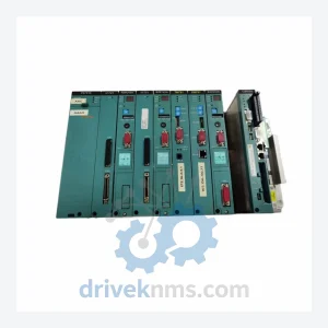
Toshiba TN721 GTN721 is listed for Monitoring Systems RFQ review. Confirm quantity, condition and destination before quotation.
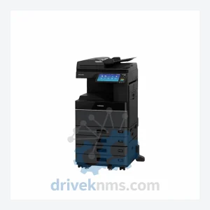
Toshiba V2MM AP012- H2184212 S10MM is listed for Monitoring Systems RFQ review. Confirm quantity, condition and destination before quotation.