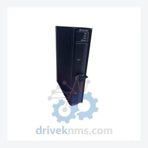
Triconex SDO3411 S2 Digital Output Module
Commercial availability is handled through direct RFQ, model verification and export-oriented follow-up rather than public cart checkout.
Model: 9662-110
Product Overview
Commercial availability is handled through direct RFQ, model verification and export-oriented follow-up rather than public cart checkout.
Datasheet Preview
Use attached product manuals when available. If the manual is not public yet, request the full file directly through RFQ.
Commercial Path
Product pages on DRIVEKNMS are designed to verify model, brand and series first, then move the buyer into one clean quotation path.
Technical Dossier
| Attribute | Detail |
|---|---|
| Manufacturer | TRICONEX (Schneider Electric) |
| Part Number | 9662-110 |
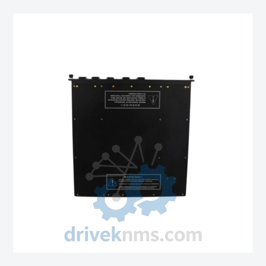
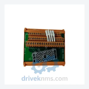
| Description | Panel Field Termination Assembly |
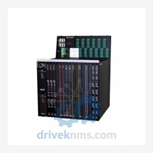
| Platform Compatibility | TRICONEX Tricon TMR Safety System |
| Country of Origin | United States |
| Product Status | Discontinued / Obsolete |
| Condition Available | New (sealed) / Refurbished (tested) |
Note: Electrical parameters specific to this assembly are not published in open documentation. DriveKNMS does not fabricate specifications. Buyers requiring detailed electrical data should reference the original TRICONEX Tricon hardware manual or contact our technical team with their system configuration.
The TRICONEX Tricon platform has been the backbone of safety instrumented systems in high-hazard process industries for decades. Its TMR architecture — where three independent processing channels vote on every output — delivers the fault tolerance required for SIL 2 and SIL 3 applications. The 9662-110 Panel Field Termination is the physical interface layer between field instrument wiring and the Tricon I/O modules. Without a functioning termination assembly, the I/O channel is inoperable, regardless of the condition of the logic solver or power supply.
How to extend the service life of a TRICONEX Tricon system by 5 to 10 years through strategic spare parts management:
Plant managers and reliability engineers operating legacy Tricon installations should treat the following as a structured asset protection protocol, not a temporary workaround.
4. Document firmware and configuration baselines. Before any hardware swap, ensure that the existing system configuration, I/O mapping, and cause-and-effect logic are fully documented and backed up. A like-for-like hardware replacement should require no re-engineering, but configuration records must be current.
5. Engage a qualified functional safety engineer for any non-routine replacement. For SIL-rated loops, any hardware change — even a direct replacement — should be reviewed against the original safety requirements specification to confirm that the replacement does not alter the safety function.
This protocol does not require capital expenditure. It requires planning. Facilities that execute it systematically can operate legacy Tricon systems reliably for an additional 5 to 10 years beyond the point at which most organizations begin to consider forced retirement.
Step 1 – Electrolytic Capacitor Assessment: Aged power supply and signal conditioning circuits are inspected for capacitor bulging, leakage, and ESR degradation. Capacitor failure is the leading cause of latent faults in legacy industrial electronics. Units with suspect capacitors are either reconditioned or rejected.
Step 2 – Firmware Version Verification: Where applicable, firmware revision is confirmed against the known compatible versions for the target Tricon system generation. Mismatched firmware can cause communication faults or prevent module recognition by the main processor.
Step 3 – Connector and Pin Inspection: All field-side and backplane connectors are inspected under magnification for corrosion, pin deformation, and contamination. Corroded pins are the most common cause of intermittent faults in termination assemblies that have been in storage or removed from service.
Step 5 – Packaging and ESD Protection: All units are packaged in anti-static bags with desiccant and labeled with part number, condition grade, and test date prior to shipment.
Q: How do I confirm the unit is genuine TRICONEX and not a counterfeit?
A: All units sourced by DriveKNMS are inspected for manufacturer markings, date codes, and board-level construction consistent with genuine TRICONEX production. We do not source from unverified brokers. Documentation of provenance is available for units where supply chain records exist.
Related Paths
Commercial availability is handled through direct RFQ, model verification and export-oriented follow-up rather than public cart checkout.
Commercial availability is handled through direct RFQ, model verification and export-oriented follow-up rather than public cart checkout.
Commercial availability is handled through direct RFQ, model verification and export-oriented follow-up rather than public cart checkout.