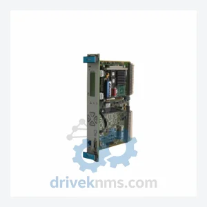
Vibro-Meter VM600 CPU-M 200-595-075-122 CPU Card – Obsolete VM600 Spare Part
Vibro-Meter VM600 CPU-M 200-595-075-122 CPU Card – Obsolete VM600 Spare Part When the CPU-M card in a VM600 rack fails,…
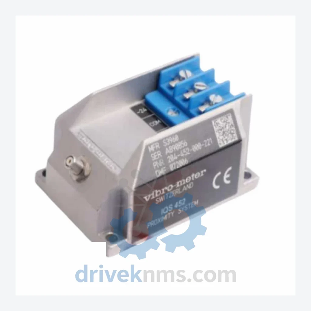
Model: IQS452 204-452-000-221
Product Overview
Commercial availability is handled through direct RFQ, model verification and export-oriented follow-up rather than public cart checkout.
Datasheet Preview
Use attached product manuals when available. If the manual is not public yet, request the full file directly through RFQ.
Commercial Path
Product pages on DRIVEKNMS are designed to verify model, brand and series first, then move the buyer into one clean quotation path.
Technical Dossier
The VIBRO-METER IQS452 is a signal amplifier module developed by Meggitt SA (formerly Vibro-Meter SA), headquartered in Fribourg, Switzerland. The IQS452 series occupies a critical position in continuous vibration monitoring systems deployed across global heavy industry: petrochemical refineries, nuclear power stations, offshore platforms, and large-scale rotating machinery installations. These modules interface directly with piezoelectric accelerometers and velocity transducers, conditioning raw sensor signals into standardized 4–20 mA or voltage outputs compatible with DCS and safety instrumented systems (SIS). The IQS452 platform is designed for installation within the VM600 rack-based monitoring chassis, operating in conjunction with the MPC4, RPS6U, and IOC4T cards. Its architecture supports continuous online monitoring without process interruption, a mandatory requirement in API 670-compliant machinery protection systems. Installed base spans facilities operated by major energy and chemical producers across Europe, the Middle East, and Asia-Pacific, making long-term spare parts availability a critical operational concern.
The IQS452 series succeeded earlier Vibro-Meter signal conditioning platforms including the IQS421 and IQS431 families. The architectural transition introduced modular channel configuration, allowing a single card format to address single-channel, dual-channel, and multi-range measurement requirements through variant suffix coding rather than separate hardware platforms. Early IQS452 variants (suffix -0x1) were optimized for velocity transducer inputs with fixed gain stages. Subsequent revisions introduced programmable gain amplification and extended frequency response to accommodate high-frequency accelerometer inputs required for bearing fault detection (suffix -2xx and -3xx variants). Integration with the VM600 rack's internal communication bus (VME-based backplane) remained consistent across all hardware revisions, ensuring backward compatibility within existing rack installations. As of 2024, the IQS452 series is classified as a mature/end-of-active-production product line. Meggitt has transitioned new installations toward the VM600 MPC4 integrated platform; however, the IQS452 remains the dominant installed module type in legacy VM600 racks globally. No direct plug-compatible replacement exists for the IQS452 form factor, making OEM-equivalent and refurbished spare parts the primary maintenance pathway for operators committed to existing rack infrastructure.
The following SKUs represent the documented IQS452 variant range, classified by channel configuration and input type. Each variant is defined by its 15-digit order code suffix.
IQS452 204-452-000-011: Single-channel velocity input, fixed gain, 4–20 mA output, standard range.
IQS452 204-452-000-021: Single-channel velocity input, extended range, dual output (mA + voltage).
IQS452 204-452-000-031: Single-channel accelerometer input, IEPE/ICP® compatible, programmable gain.
IQS452 204-452-000-041: Single-channel accelerometer input, charge mode (non-IEPE), high-temperature transducer compatible.
IQS452 204-452-000-051: Single-channel displacement proxy input, eddy-current transducer interface, 0–10 V output.
IQS452 204-452-000-111: Dual-channel velocity input, independent gain per channel, 4–20 mA outputs.
IQS452 204-452-000-121: Dual-channel velocity input, extended frequency response (2–1000 Hz), dual mA output.
IQS452 204-452-000-131: Dual-channel IEPE accelerometer input, programmable bandpass filter, dual voltage output.
IQS452 204-452-000-141: Dual-channel charge-mode accelerometer input, isolated signal paths, dual mA output.
IQS452 204-452-000-201: Single-channel, high-sensitivity velocity input, low-noise amplifier stage, SIL-2 rated output.
IQS452 204-452-000-211: Single-channel IEPE input, integrated RMS computation, 4–20 mA RMS output.
IQS452 204-452-000-221: Single-channel signal amplifier, dual-range velocity/acceleration input, programmable output scaling, VM600 backplane bus interface.
IQS452 204-452-000-231: Single-channel, wide-band accelerometer input, 1 Hz–10 kHz bandwidth, voltage output.
IQS452 204-452-000-241: Single-channel, tachometer/speed input conditioning, pulse-to-analog conversion, 4–20 mA output.
IQS452 204-452-000-301: Dual-channel, mixed input (velocity + displacement), independent signal paths, dual 4–20 mA output.
IQS452 204-452-000-311: Dual-channel, mixed input (IEPE + charge mode), selectable gain, dual voltage output.
IQS452 204-452-000-321: Dual-channel, high-isolation input stage, suitable for hazardous area transducer loops (ATEX-compatible wiring).
Each IQS452 module processed by DriveKNMS undergoes a structured test protocol specific to the VM600 backplane architecture. Testing procedures include: (1) Backplane bus communication verification using a VM600 rack test fixture to confirm VME interface integrity; (2) Input channel functional test — each signal input path is stimulated with a calibrated reference signal (velocity: 10 mV/mm/s, acceleration: 10 mV/g) and output linearity is verified across the full measurement range; (3) Output calibration check — 4–20 mA and voltage outputs are measured at 0%, 25%, 50%, 75%, and 100% of rated input to confirm gain accuracy within ±0.5%; (4) Isolation resistance test — input-to-output and channel-to-channel isolation verified at 500 VDC; (5) Thermal cycling — modules are operated across the rated temperature range (0°C to +60°C) to identify latent component failures; (6) Final functional burn-in — 24-hour continuous operation under rated load prior to release. All test records are retained and available upon request with each unit shipment.
© 2026 DriveKNMS. All trademarks belong to their respective owners. Specifications are for reference only and subject to change without notice. Verify all parameters against official documentation before installation.
Related Paths
Vibro-Meter VM600 CPU-M 200-595-075-122 CPU Card – Obsolete VM600 Spare Part When the CPU-M card in a VM600 rack fails,…
VIBRO-METER CMC16 Series: Comprehensive Module Range and Technical Overview The VIBRO-METER CMC16 series is a rack-mounted condition monitoring platform engineered…
VIBRO-METER VM600 CMC16 200-530-023-014 / 200-530-100-014: Securing Supply Continuity for Mission-Critical Condition Monitoring Systems The VIBRO-METER VM600 CMC16 (Part Numbers:…