
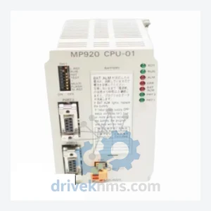
Yaskawa JEPMC-CP200 MP2000 Series Controller Module
Yaskawa JEPMC-CP200 is listed for JEPMC-CP200 MP2000 Series RFQ review. Confirm quantity, condition and destination before quotation.
RFQ-ready industrial model
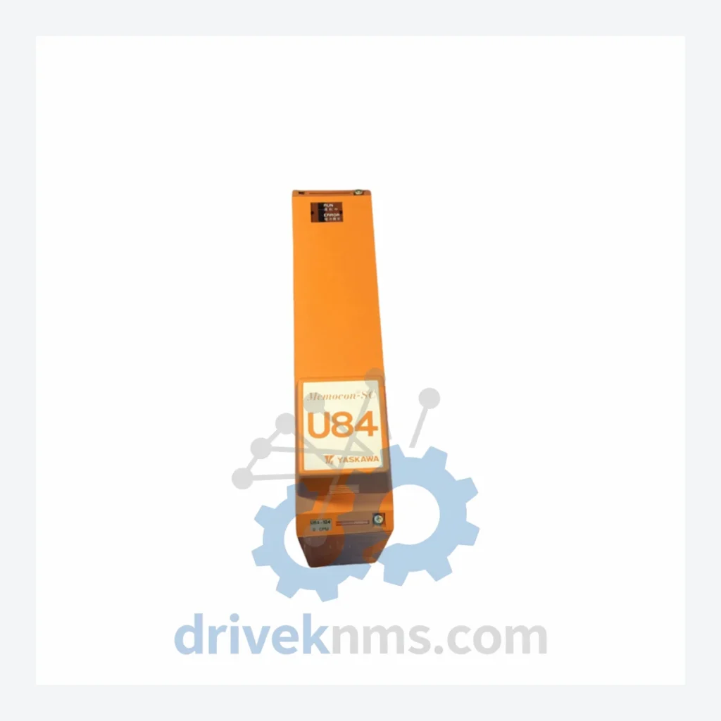
Model: DDSCR-U84-124
Product Overview
Commercial availability is handled through direct RFQ, model verification and export-oriented follow-up rather than public cart checkout.
Datasheet Preview
Use attached product manuals when available. If the manual is not public yet, request the full file directly through RFQ.
Commercial Path
Product pages on DRIVEKNMS are designed to verify model, brand and series first, then move the buyer into one clean quotation path.
Technical Dossier
The DDSCR series was introduced as part of YASKAWA's transition from analog-based process control to fully digital distributed control systems (DCS) during the late 1980s and early 1990s. Early DDSCR hardware relied on proprietary backplane bus communication operating at fixed baud rates, with module addressing determined by physical slot position. This architecture imposed strict hardware revision compatibility constraints: CPU modules, I/O modules, and communication adapters must match within defined firmware revision bands to maintain bus integrity.
Mid-generation revisions introduced enhanced diagnostic registers and expanded memory addressing, enabling larger control loop counts per CPU node. Later variants added support for YASKAWA's MECHATROLINK communication protocol extensions, bridging the DDSCR platform toward integration with motion control subsystems. However, the core backplane electrical specification remained unchanged across generations, meaning physical module substitution is possible between certain revision ranges — a critical factor for maintenance engineers sourcing replacement parts for aging installations.
CPU & Controller Modules
Digital Input (DI) Modules
Digital Output (DO) Modules
Analog Input (AI) Modules
Analog Output (AO) Modules
Communication & Network Adapter Modules
Power Supply Modules
DDSCR modules present specific test challenges due to their proprietary backplane bus protocol and slot-addressed communication architecture. Standard bench power-up is insufficient to validate module functionality; full operational verification requires a compatible DDSCR backplane and CPU reference unit.
DriveKNMS employs a dedicated DDSCR test rig replicating the original backplane electrical environment. Each CPU module, including the DDSCR-U84-124, undergoes the following verification sequence: power rail integrity check (3.3V, 5V, 12V backplane rails); bus communication handshake confirmation; firmware version readback and logging; I/O channel functional test (for I/O modules); 48-hour burn-in under simulated cyclic load; and final visual inspection per IPC-A-610 Class 2 criteria. All tested units are issued a DriveKNMS test certificate with date, technician ID, and pass/fail data for each test stage.
Continue The Model Path
Move from this exact model into the matching system hub, brand archive, model-family archive or lifecycle sourcing route before sending a final RFQ list.
Related Paths
Yaskawa JEPMC-CP200 is listed for JEPMC-CP200 MP2000 Series RFQ review. Confirm quantity, condition and destination before quotation.
Yaskawa YASKAWA CP-9200SH/CPU integrated controller is listed for PLC Modules RFQ review. Confirm quantity, condition and destination before quotation.
Yaskawa JANCD-NCP01 is listed for PLC Modules RFQ review. Confirm quantity, condition and destination before quotation.