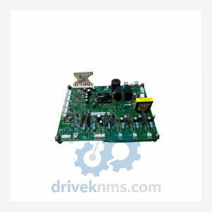
Yaskawa YPCT11065-1-3 Circuit Board – Obsolete Varispeed Series Spare Part
Yaskawa YPCT11065-1-3 Circuit Board – Obsolete Varispeed Series Spare Part When a circuit board like the YPCT11065-1-3 fails inside a…
Model: DX100 JARCR-YPC01-1
Product Overview
Commercial availability is handled through direct RFQ, model verification and export-oriented follow-up rather than public cart checkout.
Datasheet Preview
Use attached product manuals when available. If the manual is not public yet, request the full file directly through RFQ.
Commercial Path
Product pages on DRIVEKNMS are designed to verify model, brand and series first, then move the buyer into one clean quotation path.
Technical Dossier
The YASKAWA DX100 is a robot controller platform introduced by Yaskawa Electric Corporation (Motoman division) as the successor to the NX100 series. It is deployed across heavy industrial sectors including automotive body welding, chemical plant material handling, nuclear facility maintenance robotics, and refinery pipeline inspection systems. The DX100 supports up to 8 axes of coordinated motion and is compatible with the full Motoman robot arm lineup produced during its active production window (approximately 2008–2018). Its installed base spans tens of thousands of units globally, making long-term spare parts availability a critical operational concern for plant maintenance teams.
The DX100 controller architecture is built around a VME-bus-derived backplane with proprietary YASKAWA communication protocols (MECHATROLINK-II and Ethernet/IP options). It replaced the NX100's older CPU board design with a more integrated main processing unit, consolidating robot language processing (INFORM III), safety monitoring, and I/O management onto fewer boards. Key architectural milestones:
NX100 → DX100 transition (c. 2008): Introduced 32-bit processing architecture, expanded axis count support, and USB-based programming pendant interface. Backward compatibility with NX100 teach pendant programs required conversion utilities.
DX100 mid-cycle revision (c. 2012): Firmware updates introduced expanded Ethernet connectivity options and enhanced functional safety (FSU) module integration, enabling compliance with ISO 10218-1 safety standards without external safety relays in many configurations.
DX100 → YRC1000 transition (c. 2016–2018): YASKAWA introduced the YRC1000 and YRC1000micro as successors. The DX100 entered its end-of-active-production phase. Spare parts sourcing shifted from OEM channels to authorized distributors and specialist aftermarket suppliers. Compatibility between DX100 and YRC1000 boards is not direct; module substitution requires engineering verification.
For facilities operating DX100 controllers beyond the OEM support window, third-party lifecycle extension services — including board-level repair, functional testing, and certified refurbished module supply — represent the primary maintenance pathway.
The following SKUs represent verified components within the YASKAWA DX100 controller ecosystem, organized by functional category. Each entry reflects a discrete board or module with a defined role in the controller architecture.
Connection & Communication Units
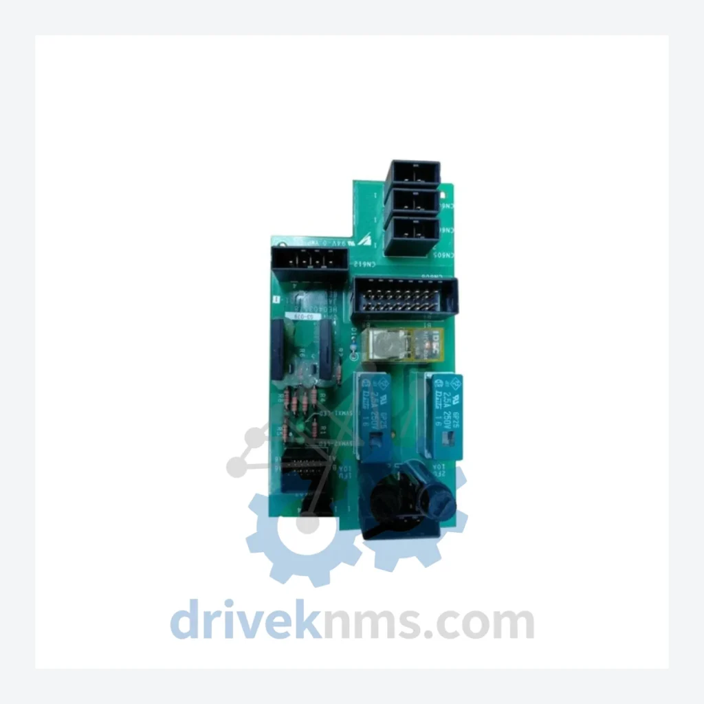
JARCR-YPC01-1: Main connection unit board; primary backplane interface for DX100 controller internal bus routing.
JARCR-YPC02: Secondary connection board; supports expanded I/O backplane communication in multi-axis configurations.
JANCD-YCP01-E: CPU board; central processing unit for robot motion calculation and INFORM III language execution.
JANCD-YCP02-E: Sub-CPU board; handles coordinated multi-robot (MRC) processing and inter-controller communication.
I/O Modules
JANCD-YIO01-E: General-purpose digital I/O board; 32 DI / 32 DO, 24VDC, used for external signal interfacing.
JANCD-YIO02-E: Expanded I/O board; supports additional discrete I/O channels for complex cell integration.
JARCR-YIO21-1: Isolated digital input module; used in high-noise industrial environments requiring signal isolation.
JARCR-YIO22-1: Isolated digital output module; relay-driven outputs for safety-critical actuator control.
Power Supply Units
JZNC-YPS01-E: Main power supply board; converts AC input to regulated DC rails for controller internal distribution.
JZNC-YPS02-E: Auxiliary power supply; provides secondary DC rail for I/O and communication subsystems.
JARCR-YPU01-1: Power unit assembly; integrated power conditioning module for DX100 base cabinet.
Safety & Servo Control
JANCD-YSF21-E: Functional safety unit (FSU); implements dual-channel safety monitoring per ISO 13849 PLd requirements.
JANCD-YSF01-E: Safety I/O board; interfaces external safety devices (E-stop, light curtains, safety mats) to FSU logic.
SGDR-AXA01A: Servo amplifier board; axis drive control for Motoman robot joint servo motors.
JANCD-YSV01-E: Servo control interface board; bridges CPU motion commands to individual axis amplifier modules.
Communication Adapters
JANCD-YEW01-E: Ethernet/IP communication board; enables integration with Allen-Bradley PLC networks and SCADA systems.
JANCD-YDP01-E: DeviceNet master board; supports legacy DeviceNet field bus topologies common in pre-2015 automotive cells.
JANCD-YPP01-E: PROFIBUS-DP interface board; used in European automotive and process industry installations.
The DX100 series reached end-of-active-production status with YASKAWA's OEM channel approximately 2018–2020. Lead times for new OEM boards — where still available — frequently exceed 16–26 weeks. For facilities requiring immediate corrective maintenance or scheduled turnaround, DriveKNMS maintains a dedicated DX100 spare parts inventory sourced through authorized distribution channels and certified refurbishment programs.
DriveKNMS lifecycle support for DX100 includes: verified-functional refurbished boards with traceability documentation; board-level repair services for CPU, I/O, and power supply modules; cross-reference matching for superseded part numbers; and exchange programs to reduce downtime during critical production windows. All DX100 inventory is stored in ESD-controlled environments and shipped with appropriate anti-static packaging.
DX100 modules present specific test challenges due to their proprietary backplane bus architecture and integrated safety logic. DriveKNMS applies the following verification procedures to all DX100 inventory prior to dispatch:
Backplane bus integrity test: Each board is seated in a DX100-compatible test rack and subjected to full MECHATROLINK-II communication cycle verification to confirm bus arbitration and data integrity.
CPU board functional test: JANCD-YCP01-E and YCP02-E boards are tested under live controller power-up sequences, including INFORM III interpreter initialization and axis parameter load verification.
I/O channel verification: All digital I/O boards are tested channel-by-channel at rated voltage (24VDC) with load simulation to confirm switching response and isolation resistance.
Power supply load test: JZNC-YPS01-E and auxiliary power boards are tested under rated load conditions across all DC output rails, with ripple and regulation measurements recorded.
Safety module validation: FSU boards (JANCD-YSF21-E, YSF01-E) are tested against dual-channel input/output logic tables to confirm safety function integrity prior to release.
Test records are retained and available upon request for quality-critical procurement processes.
Related Paths
Yaskawa YPCT11065-1-3 Circuit Board – Obsolete Varispeed Series Spare Part When a circuit board like the YPCT11065-1-3 fails inside a…
Yaskawa YPHT11014-1A Circuit Board – Obsolete Drive Control Spare Part When a Yaskawa YPHT11014-1A circuit board fails in a production…
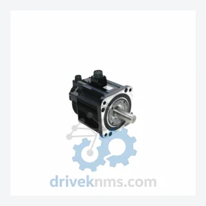
Yaskawa SGMG Series: Comprehensive Module Range and Technical Overview The Yaskawa SGMG series represents one of the most widely deployed…