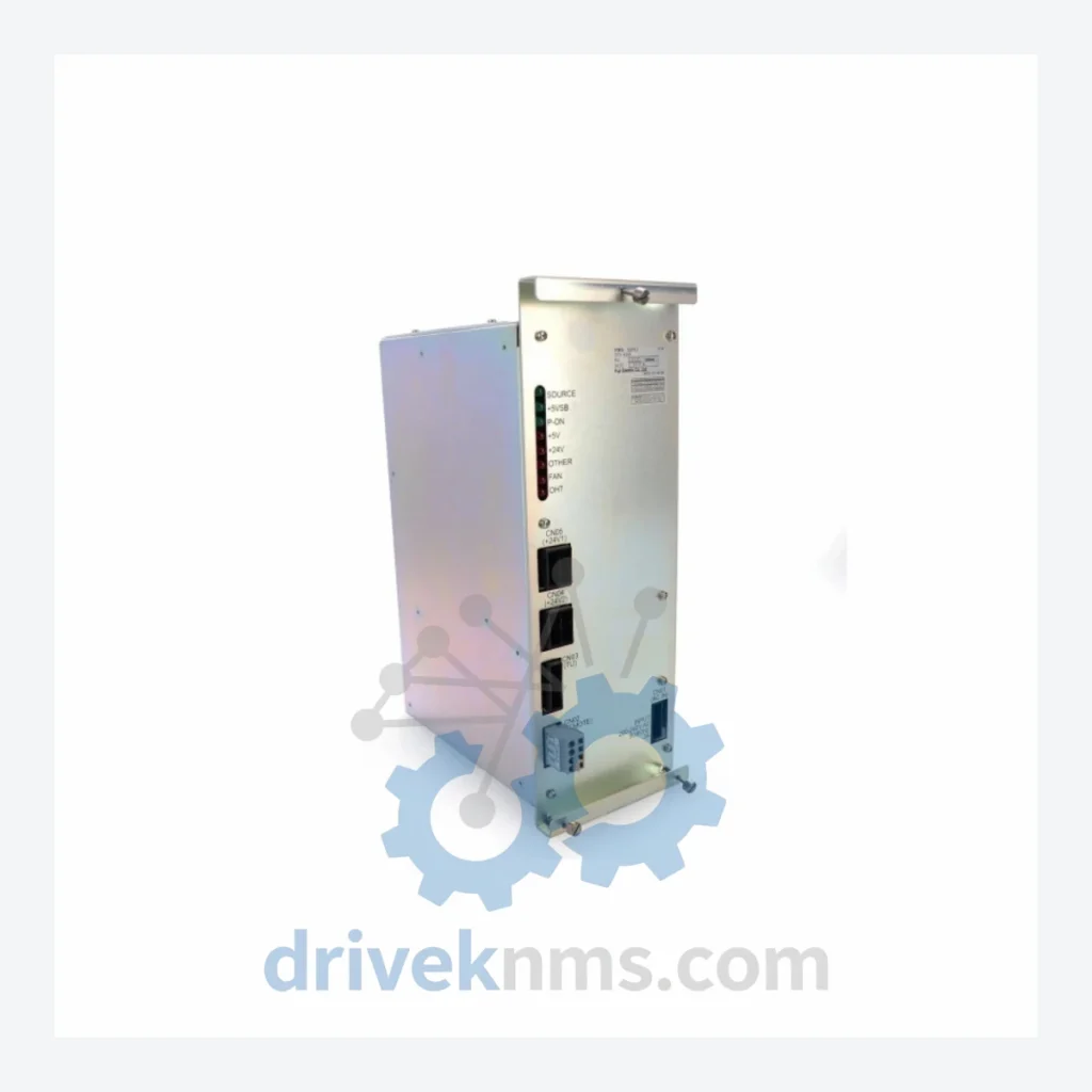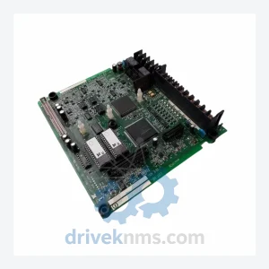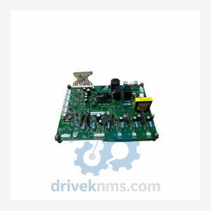
Yaskawa JZRCR-NTU30B-1

Model: NX100 JZRCR-NTU30B-1

Brand Yaskawa
Model NX100 JZRCR-NTU30B-1
RFQ-ready model route Obsolete and surplus sourcing Export follow-up by model list

Product Overview

Commercial availability is handled through direct RFQ, model verification and export-oriented follow-up rather than public cart checkout.

Datasheet Preview

Datasheet Preview

Use attached product manuals when available. If the manual is not public yet, request the full file directly through RFQ.

Request Full Manual

Commercial Path

Use This Page To Confirm The Model, Then Move To RFQ

Product pages on DRIVEKNMS are designed to verify model, brand and series first, then move the buyer into one clean quotation path.

Technical Dossier

Product Details And Specifications

Yaskawa NX100 Series Technical Notes

The Evolution of NX100 Architecture

The NX100 controller succeeded the XRC (1998–2003) and introduced a modular rack-based hardware architecture that separated power distribution, CPU processing, servo amplifier control, and I/O management into discrete, field-replaceable modules. This design philosophy allowed maintenance engineers to replace individual failed boards without full controller replacement — a significant operational advantage in high-uptime environments.

The NX100 backplane uses a proprietary high-speed serial bus (MECHATROLINK-II compatible in later revisions) to coordinate inter-module communication. Early NX100 units (pre-2006) used a parallel bus architecture that is electrically incompatible with post-2007 board revisions — a critical compatibility constraint when sourcing replacement modules for legacy installations.

NX100 Full Catalog & Functionalities (SKU List)

The following SKUs represent verified, commonly encountered modules within the Yaskawa NX100 controller ecosystem. Modules are categorized by functional role.

Power Supply Units

  • JZRCR-NTU30B-1: Control cabinet primary power supply unit; 24VDC regulated output for CPU and I/O bus rails.
  • JZRCR-NTU31B-1: Servo power supply board; provides DC bus voltage to servo amplifier section.
  • JZRCR-NTU32B-1: Auxiliary power distribution board; secondary rail regulation for peripheral I/O modules.

CPU & Main Processing Boards

  • JANCD-NCP01B-1: Main CPU board; dual-processor motion control and system management.
  • JANCD-NCP01-1: Earlier revision of main CPU board; parallel bus architecture, pre-2006 compatibility.
  • JANCD-NIF01B: Network interface board; Ethernet and DeviceNet communication management.
  • JANCD-NIF01: Earlier network interface revision; supports DeviceNet only, no Ethernet port.

I/O Modules — Digital Input (DI)

  • JANCD-NIO01B: 32-channel digital I/O board; 24VDC sink/source configurable inputs.
  • JANCD-NIO02B: Expanded 64-channel digital I/O module; used in high-density I/O configurations.
  • JZNC-NIO01B: Safety I/O board; dual-channel safety input processing for E-stop and safety gate circuits.

I/O Modules — Analog Input/Output (AI/AO)

  • JANCD-NAO01B: 4-channel analog output module; ±10V / 4–20mA configurable per channel.
  • JANCD-NAI01B: 4-channel analog input module; 12-bit resolution, ±10V input range.

Communication & Fieldbus Adapters

  • JANCD-NIF02B: PROFIBUS-DP slave adapter; supports up to 244 bytes I/O exchange.
  • JANCD-NIF03B: CC-Link slave communication board; used in Japanese domestic automotive line integrations.
  • JANCD-NIF04B: EtherNet/IP adapter board; later-production NX100 units only.

Servo Amplifier & Axis Control

  • SGDR-AXA01A: Servo amplifier control board; axis 1–3 drive interface for standard 6-axis configurations.
  • SGDR-AXA02A: Servo amplifier control board; axis 4–6 drive interface.
  • JANCD-NCP02B: Coordinated motion sub-processor; required for multi-robot synchronized operation.

Quality Control for the NX100 Range

NX100 modules present specific test challenges due to the platform's proprietary backplane bus protocol and multi-board interdependencies. DriveKNMS applies the following verification procedures to all NX100 inventory:

  • Backplane Bus Integrity Test: Each board is seated in a reference NX100 rack and subjected to full bus communication verification. Boards that fail to enumerate on the backplane are rejected regardless of visual condition.
  • Power Rail Verification: Power supply units (including JZRCR-NTU30B-1) are load-tested at 80% rated capacity for a minimum of 2 hours. Output ripple, regulation accuracy, and thermal performance are logged.
  • Functional I/O Cycling: All digital and analog I/O boards are cycled through full channel activation sequences. Channel-level fault isolation is performed on any board showing non-uniform response.
  • Firmware Revision Logging: CPU and network boards are read for embedded firmware version. Revision data is recorded and disclosed to the customer prior to shipment to prevent compatibility conflicts with existing controller configurations.
  • Visual and Component Inspection: All boards are inspected under magnification for capacitor bulge, solder joint fatigue, corrosion on edge connectors, and trace damage — failure modes common in NX100 units recovered from high-humidity or high-vibration environments.

Continue The Model Path

Use system, brand and series routes to compare related published models.

Move from this exact model into the matching system hub, brand archive, model-family archive or lifecycle sourcing route before sending a final RFQ list.

WhatsApp Prefilled Inquiry Email sale@driveknms.com Phone +86 18359293191 Top Back To Top