
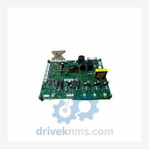
Yaskawa YPCT11065-1-3 Circuit Board – Obsolete Varispeed Series Spare Part
Yaskawa YPCT11065-1-3 is listed for Servo Drives RFQ review. Confirm quantity, condition and destination before quotation.
RFQ-ready industrial model
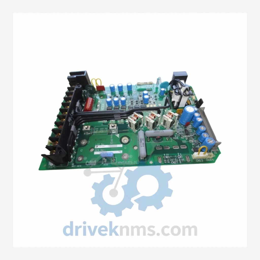
Model: YPHT31133-1E ETP615455
Product Overview
Commercial availability is handled through direct RFQ, model verification and export-oriented follow-up rather than public cart checkout.
Datasheet Preview
Use attached product manuals when available. If the manual is not public yet, request the full file directly through RFQ.
Commercial Path
Product pages on DRIVEKNMS are designed to verify model, brand and series first, then move the buyer into one clean quotation path.
Technical Dossier
DriveKNMS maintains a carefully sourced inventory of this board. If you are reading this, you likely already understand what is at stake. Act before the unit count reaches zero.
RFQ support for obsolete parts: Send the model number, required quantity and destination so DriveKNMS can confirm sourcing options before quotation.
| Parameter | Detail |
|---|---|
| Manufacturer | Yaskawa Electric Corporation |
| Part Number | YPHT31133-1E |
| PCB Reference | ETP615455 |
| Component Type | Driver Board / Gate Drive Card |
| Compatible Drive Series | Yaskawa Varispeed (legacy series) |
| Country of Origin | Japan |
| Production Status | Discontinued – No longer manufactured by Yaskawa |
| Typical System Context | Yaskawa Varispeed F7, G7, and earlier Varispeed series AC drives used in industrial automation, HVAC, and process control applications |
The Yaskawa Varispeed platform was deployed across thousands of industrial facilities worldwide throughout the 1990s and 2000s — in steel mills, water treatment plants, paper lines, chemical processing, and building automation systems. Many of these installations remain in service today, not because replacement is impossible, but because the cost and risk of replacement are prohibitive.
The YPHT31133-1E driver board sits at the core of the drive's IGBT gate control circuit. It translates control signals into the precise switching commands that govern motor output. When this board degrades — through capacitor aging, thermal cycling fatigue, or moisture ingress — the drive either faults repeatedly or fails to start. There is no firmware patch. There is no workaround. The board must be replaced.
Yaskawa's own service network no longer stocks this component. Third-party repair shops that once rebuilt these boards are increasingly unable to source the original semiconductors. The window for obtaining a verified replacement unit is narrowing each year. Facilities that have not secured at least one spare are operating with an unquantified liability on their balance sheet.
For plant managers facing capital budget constraints, the calculus is straightforward: one spare board at current market price versus a six-figure emergency upgrade under production pressure. The spare board wins every time — provided it can still be found.
Industrial automation assets — particularly variable frequency drives installed before 2005 — were engineered for 20-year service lives under controlled conditions. In practice, many are now operating well beyond that horizon. The following approach has been used by maintenance engineers to extend reliable service life without full system replacement:
1. Critical Spare Identification: Map every drive in your facility to its control board part number. Identify which boards are no longer available through OEM channels. These are your highest-priority procurement targets. The YPHT31133-1E is one such board.
2. Condition-Based Monitoring: Implement thermal imaging on drive cabinets quarterly. Rising junction temperatures on the driver board are an early indicator of capacitor degradation or dry solder joints — both of which are repairable if caught before catastrophic failure.
3. Electrolytic Capacitor Lifecycle Management: Electrolytic capacitors on boards of this era have a rated service life of 10–15 years under nominal conditions. Boards that have been in service for 15+ years should be treated as time-limited components regardless of apparent function. Proactive replacement of the entire board — rather than waiting for failure — is the lower-risk strategy.
4. Controlled Storage of Spare Boards: Spare boards should be stored in anti-static packaging, in a climate-controlled environment (15–25°C, <60% RH). Boards stored improperly for extended periods can develop oxide layers on connector pins that cause intermittent faults upon installation.
5. Firmware and Configuration Documentation: Before any board swap, document the drive's parameter set completely. While the YPHT31133-1E is a hardware component and does not itself carry drive parameters, the surrounding control architecture may require parameter verification after a board replacement.
Facilities that execute this strategy systematically can defer capital replacement programs by 5–10 years with a fraction of the cost — and without the production risk of a forced cutover.
DriveKNMS applies a 5-step inspection protocol to every obsolete board before it is offered for sale:
Step 1 – Visual Inspection: Full board examination under magnification. Checks for cracked solder joints, burnt components, delamination, and physical damage to the PCB substrate.
Step 2 – Electrolytic Capacitor Assessment: Capacitors are tested for ESR (equivalent series resistance) and capacitance value. Boards with out-of-tolerance capacitors are either reconditioned with OEM-equivalent components or removed from inventory.
Step 3 – Connector and Pin Integrity: All edge connectors and pin headers are inspected for corrosion, oxidation, and mechanical deformation. Affected contacts are cleaned using appropriate contact restoration methods.
Step 4 – Firmware Version Verification: Where applicable, onboard firmware or EPROM versions are documented and disclosed to the buyer prior to shipment. Compatibility with the target drive revision is confirmed where drive model information is provided.
Step 5 – Functional Cross-Reference: Board part number and PCB reference are cross-checked against known compatible drive configurations to confirm the unit matches the buyer's application before dispatch.
Q: Should I buy more than one unit?
A: For any drive that is critical to production continuity, holding a minimum of one spare board is standard practice. For facilities with multiple drives using this board, a ratio of one spare per three installed units is a reasonable starting point. Given the declining availability of this part, procurement decisions made today will be more cost-effective than those made under emergency conditions.
Continue The Model Path
Move from this exact model into the matching system hub, brand archive, model-family archive or lifecycle sourcing route before sending a final RFQ list.
Related Paths
Yaskawa YPCT11065-1-3 is listed for Servo Drives RFQ review. Confirm quantity, condition and destination before quotation.
Yaskawa YPHT11014-1A is listed for Servo Drives RFQ review. Confirm quantity, condition and destination before quotation.
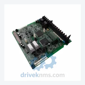
Yaskawa YPCT11065-1-4 is listed for G7 / F7 Series RFQ review. Confirm quantity, condition and destination before quotation.