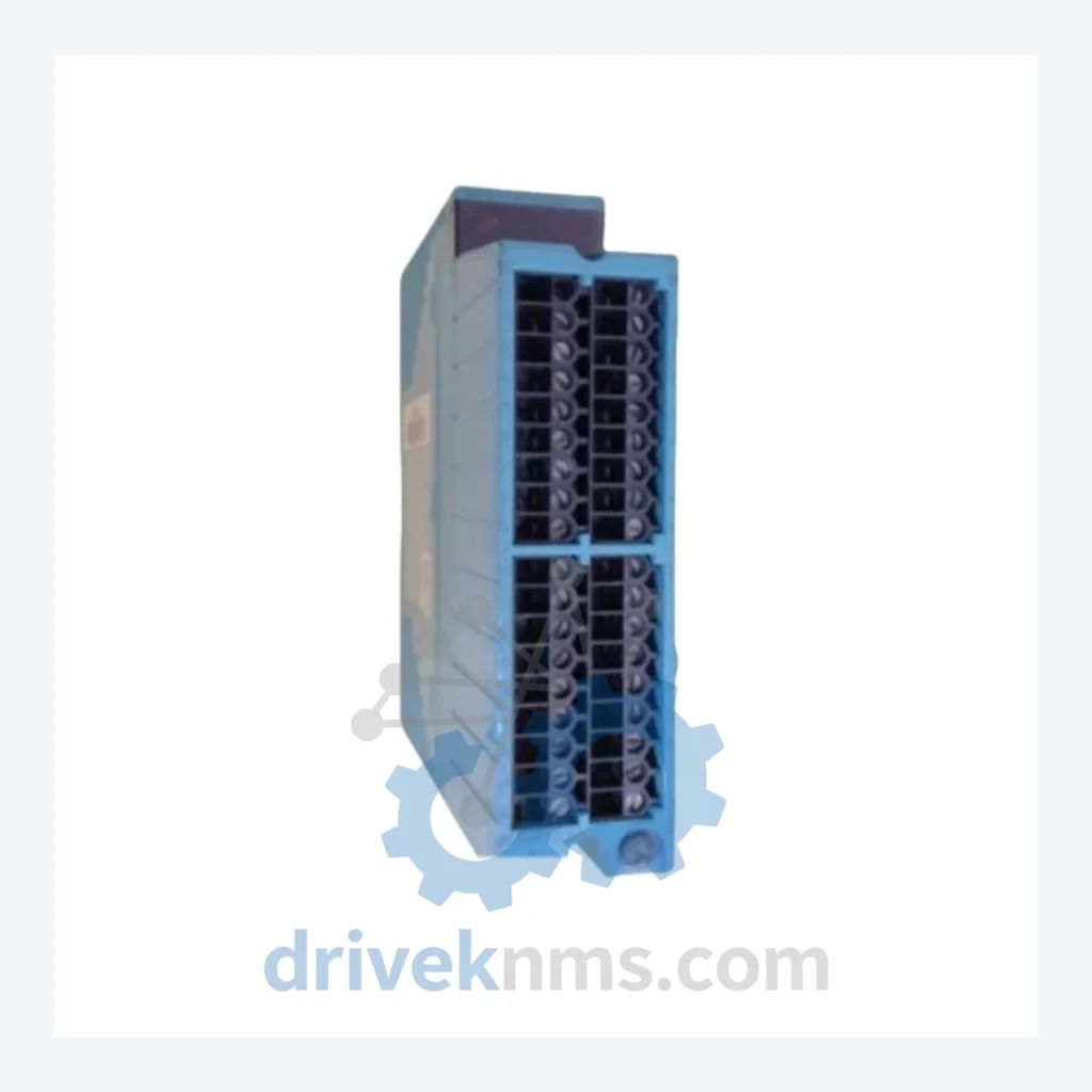
Yokogawa NFAI141-S00 S2 Analog Input Module

Model: NFAI141-S00 S2

Brand Yokogawa
Model NFAI141-S00 S2
RFQ-ready model route Obsolete and surplus sourcing Export follow-up by model list

Product Overview

Commercial availability is handled through direct RFQ, model verification and export-oriented follow-up rather than public cart checkout.

Datasheet Preview

Datasheet Preview

Use attached product manuals when available. If the manual is not public yet, request the full file directly through RFQ.

Request Full Manual

Commercial Path

Use This Page To Confirm The Model, Then Move To RFQ

Product pages on DRIVEKNMS are designed to verify model, brand and series first, then move the buyer into one clean quotation path.

Technical Dossier

Product Details And Specifications

Yokogawa NFAI141 Series Technical Notes

The Evolution of NFAI141 Architecture

The NFAI141 module traces its lineage to the Yokogawa CENTUM CS 3000 platform introduced in the late 1990s, which standardized the node-based I/O architecture using the Vnet/IP control network. Early NFAI141 revisions (suffix -S00) established the baseline 16-channel analog input specification with HART pass-through capability. Subsequent suffix variants introduced incremental improvements in channel isolation, EMC compliance ratings, and firmware compatibility with CENTUM VP R4.x and R6.x releases.

NFAI141 Full Catalog & Functionalities (SKU List)

The following SKUs represent the verified NFAI141 series and closely related CENTUM VP analog I/O modules. Each entry reflects a distinct hardware revision, channel configuration, or functional variant within the Yokogawa field I/O module ecosystem.

Analog Input Modules (AI)

  • NFAI141-S00 S2: 16-ch analog input, 4–20 mA/voltage, HART, CENTUM VP FCS compatible, HW rev S2
  • NFAI141-S00 S1: 16-ch analog input, 4–20 mA/voltage, HART, HW rev S1, CS 3000 / VP R4.x
  • NFAI141-S00 S3: 16-ch analog input, 4–20 mA/voltage, HART, HW rev S3, VP R6.x firmware
  • NFAI141-S10: 16-ch analog input with enhanced channel isolation, intrinsically safe variant
  • NFAI141-S20: 16-ch analog input, extended temperature range, offshore/hazardous area rated
  • NFAI841-S00: 8-ch high-density analog input, 4–20 mA, HART multiplexed, CENTUM VP FCS
  • NFAI841-S10: 8-ch analog input, IS barrier integrated, Zone 1 hazardous area deployment

Analog Output Modules (AO)

  • NFAO141-S00: 16-ch analog output, 4–20 mA, HART, CENTUM VP FCS, standard revision
  • NFAO141-S00 S2: 16-ch analog output, 4–20 mA, HART, HW rev S2, VP R5.03+
  • NFAO841-S00: 8-ch analog output, 4–20 mA, HART, high-density FCS node

Digital Input / Digital Output Modules (DI/DO)

  • NFDI141-S00: 32-ch digital input, 24 VDC, dry contact / wet contact selectable, CENTUM VP
  • NFDI141-S10: 32-ch digital input, IS-rated, Zener barrier compatible, Zone 1
  • NFDO141-S00: 32-ch digital output, 24 VDC transistor, CENTUM VP FCS node
  • NFDO141-S10: 32-ch digital output, relay output variant, 250 VAC/30 VDC contact rating

Communication & Power Modules

  • NFCP701-S00: Field control station (FCS) CPU module, CENTUM VP, Vnet/IP dual-redundant
  • NFPS701-S00: FCS power supply module, 24 VDC output, redundant pair configuration
  • NFBU711-S00: Node unit base module, 16-slot I/O bus backplane, CENTUM VP FCS

Quality Control for the NFAI141 Range

NFAI141 modules incorporate a multi-layer backplane bus architecture connecting the analog front-end (AFE) signal conditioning circuitry to the FCS node communication interface. DriveKNMS applies a structured test protocol specific to this module family:

  • Channel-level signal injection: Each of the 16 analog input channels is stimulated with calibrated 4 mA, 12 mA, and 20 mA reference signals. Output digital values are verified against the module's published accuracy specification (±0.1% of span).
  • HART communication verification: HART pass-through functionality is tested on a minimum of four channels per module using a HART communicator to confirm secondary variable transmission integrity.
  • Backplane bus continuity: The node bus connector (96-pin DIN) is inspected for pin deformation and contact oxidation. Bus communication is verified under simulated FCS node load conditions.
  • Firmware revision identification: Hardware suffix (S1/S2/S3) is confirmed via module label and internal firmware register read-back to prevent suffix mismatch in target FCS configurations.
  • Burn-in cycle: Modules are subjected to a 48-hour powered burn-in at 40°C ambient to screen for early-life component failures prior to dispatch.

Continue The Model Path

Use system, brand and series routes to compare related published models.

Move from this exact model into the matching system hub, brand archive, model-family archive or lifecycle sourcing route before sending a final RFQ list.

WhatsApp Prefilled Inquiry Email sale@driveknms.com Phone +86 18359293191 Top Back To Top