
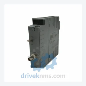
Yokogawa VC401-10 Vnet Coupler Unit – V-net Bus Interface Module
Yokogawa VC401-10 is listed for Communication Modules RFQ review. Confirm quantity, condition and destination before quotation.
RFQ-ready industrial model
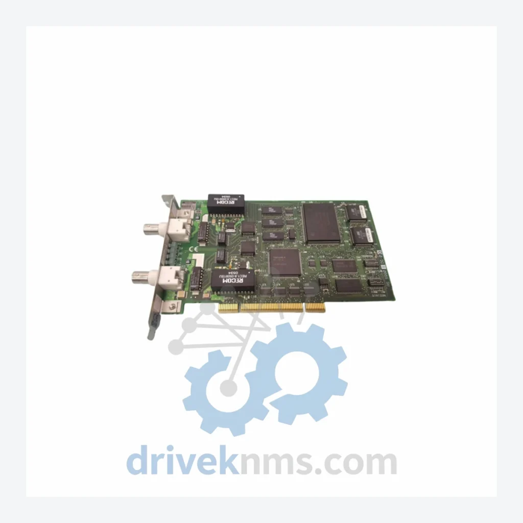
Model: VF701 S3/VF701 S1
Product Overview
Commercial availability is handled through direct RFQ, model verification and export-oriented follow-up rather than public cart checkout.
Datasheet Preview
Use attached product manuals when available. If the manual is not public yet, request the full file directly through RFQ.
Commercial Path
Product pages on DRIVEKNMS are designed to verify model, brand and series first, then move the buyer into one clean quotation path.
Technical Dossier
The Yokogawa VF701 series communication cards are purpose-built interface modules for the CENTUM VP and CENTUM CS 3000 Distributed Control Systems (DCS), which are deployed across critical heavy-industry infrastructure worldwide — including petrochemical complexes, nuclear power facilities, offshore platforms, and large-scale refinery operations. The VF701 series occupies a foundational role in Yokogawa's field communication architecture, providing the physical and logical bridge between the DCS controller domain and field device networks. Installed base counts for CENTUM CS 3000 and CENTUM VP systems run into the tens of thousands of units globally, making VF701-series cards among the most frequently sourced spare communication modules in the industrial automation aftermarket.
The VF701 communication card line was introduced as part of Yokogawa's CENTUM CS 3000 platform, which entered the market in the late 1990s as a successor to the CENTUM-XL and CENTUM CS systems. The VF701 S1 represents the first-generation variant, designed for Vnet/IP and RS-485-based field bus communication within early CS 3000 field control stations (FCS). The VF701 S3 is the revised second-generation variant, incorporating enhanced noise immunity, improved bus arbitration logic, and extended compatibility with CENTUM VP — Yokogawa's current-generation DCS platform released in 2008.
Both variants share the same physical form factor and backplane connector pinout, enabling direct slot-for-slot replacement in most FCS chassis configurations. However, firmware compatibility must be verified against the FCS software version before substitution. The VF701 series interfaces with the Vnet/IP real-time Ethernet backbone at the supervisory level while simultaneously managing lower-level field bus segments, making it a dual-domain communication node within the CENTUM architecture. As CENTUM CS 3000 has entered its extended support phase and CENTUM VP continues to receive active development, VF701 cards now serve both active production systems and long-term maintenance pools for aging CS 3000 installations.
The following SKUs represent verified, commonly sourced modules within the Yokogawa VF701 and associated CENTUM CS 3000 / CENTUM VP communication and I/O module ecosystem. Each entry reflects a distinct hardware configuration.
Communication Cards (Vnet / Field Bus Interface)
CPU / Controller Modules
Analog Input / Output Modules
Digital Input / Output Modules
Power Supply Modules
VF701 communication cards present specific test challenges due to their dual-domain architecture — simultaneous Vnet/IP Ethernet interface and RS-485 field bus segment management. DriveKNMS applies a structured multi-stage inspection protocol to all VF701 units prior to dispatch.
Stage 1 — Visual and Physical Inspection: Board-level examination for corrosion, capacitor degradation, connector pin integrity, and conformal coating condition. Stage 2 — Powered Functional Test: Each card is energized in a CENTUM-compatible test chassis. Vnet/IP link establishment, bus arbitration response, and LED status indicators are verified against Yokogawa factory test specifications. Stage 3 — Communication Loop Test: A simulated FCS environment is used to confirm full duplex data exchange across both the Vnet/IP port and the RS-485 field bus segment. Stage 4 — Burn-In Cycle: Units are subjected to a minimum 48-hour continuous operation cycle under load to screen for latent component failures. Stage 5 — Revision Documentation: Hardware revision code and firmware version are recorded and included with each unit's shipment documentation to support the customer's maintenance records.
Continue The Model Path
Move from this exact model into the matching system hub, brand archive, model-family archive or lifecycle sourcing route before sending a final RFQ list.
Related Paths
Yokogawa VC401-10 is listed for Communication Modules RFQ review. Confirm quantity, condition and destination before quotation.
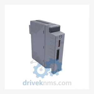
Yokogawa SB401-51 is listed for Communication Modules RFQ review. Confirm quantity, condition and destination before quotation.
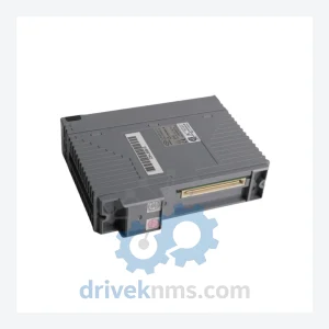
Yokogawa AAP135-S03 is listed for Communication Modules RFQ review. Confirm quantity, condition and destination before quotation.