Fluke 568-2 Infrared and Contact Thermometer – Critical Industrial Spare Part
Fluke 568-2 Infrared and Contact Thermometer – Critical Industrial Spare Part When a temperature measurement instrument fails on an active…
Model: 2423224 0050-06878 602199-104,602705-107,602200-103 602199-504
Product Overview
Commercial availability is handled through direct RFQ, model verification and export-oriented follow-up rather than public cart checkout.
Datasheet Preview
Use attached product manuals when available. If the manual is not public yet, request the full file directly through RFQ.
Commercial Path
Product pages on DRIVEKNMS are designed to verify model, brand and series first, then move the buyer into one clean quotation path.
Technical Dossier
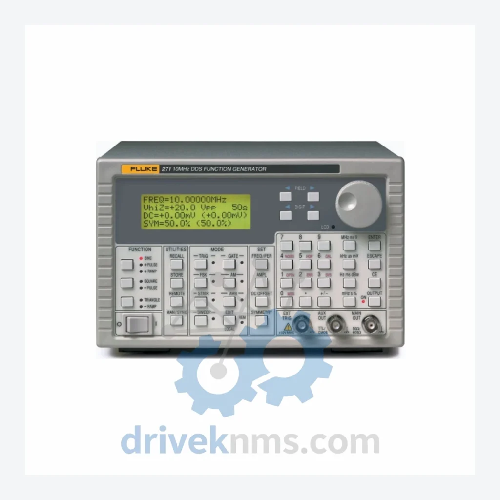
The Fluke DDS (Direct Digital Synthesis) Function Generator series occupies a well-established position in global heavy industry metrology and calibration infrastructure. Deployed across chemical processing plants, nuclear facilities, petroleum refineries, and power generation stations, these instruments serve as primary signal sources for testing, calibration, and verification of electronic control systems. The series is characterized by its high-frequency stability, low phase noise, and support for arbitrary waveform generation (ARB), making it a reference-grade tool in environments where signal integrity is non-negotiable. Part numbers within this family — including 2423224, 0050-06878, 602199-104, 602705-107, 602200-103, and 602199-504 — represent specific assembly configurations, board-level components, and accessory modules tied to the core DDS generator platform.
Fluke's DDS-based signal generation technology evolved from earlier analog VCO (Voltage-Controlled Oscillator) designs that were prevalent in test equipment through the 1980s. The transition to DDS architecture in the 1990s enabled frequency resolution down to the sub-millihertz level, phase-continuous frequency switching, and deterministic waveform output — capabilities that analog designs could not reliably deliver in industrial environments.
Early DDS generators in the Fluke lineup operated at lower clock frequencies with limited ARB memory depth, typically 4K to 16K sample points. Subsequent generations expanded ARB memory to 256K points or greater, increased output bandwidth, and added modulation modes including AM, FM, PM, FSK, and sweep. The integration of IEEE-488 (GPIB) and later RS-232 and USB interfaces allowed these instruments to be embedded into automated test systems (ATE) running LabVIEW, MATLAB, or proprietary SCADA-linked calibration routines.
Compatibility considerations are significant for facilities maintaining legacy DCS or PLC calibration benches. Older Fluke DDS units may require specific interface cards or adapter cables to communicate with modern test automation software. Board-level part numbers such as 602199-104 and 602200-103 correspond to internal PCB assemblies that are not interchangeable across all chassis revisions — cross-referencing the chassis serial number range is mandatory before ordering replacement boards.
The following part numbers represent the documented range of modules, assemblies, and accessories within the Fluke DDS Function Generator platform. Each entry reflects a distinct functional role within the instrument ecosystem:
2423224: Top-level assembly identifier for the DDS Function Generator with ARB capability, primary ordering reference.
0050-06878: Internal sub-assembly or PCB module reference, associated with signal conditioning or output stage circuitry.
602199-104: Board-level replacement assembly, revision 104; used in specific chassis production runs.
602705-107: Interface or communication module assembly, revision 107; supports instrument bus connectivity.
602200-103: Power supply or regulation board assembly, revision 103; critical for output voltage stability.
602199-504: Board-level assembly, revision 504; later production variant with updated component specifications.
Fluke 271: 10 MHz DDS Function Generator, single-channel, GPIB/RS-232 interface, 12-bit DAC, 256K ARB memory.
Fluke 272: 10 MHz DDS Function Generator with enhanced modulation modes; dual-output option available.
Fluke 273: 10 MHz DDS Function Generator with built-in frequency counter and extended ARB waveform library.
Fluke 280 Series: Arbitrary Waveform Generator platform; 50 MHz bandwidth, 14-bit vertical resolution, 256K sample ARB.
Fluke 281: Single-channel 50 MHz ARB generator; USB and GPIB standard; compatible with FlukeView software.
Fluke 282: Dual-channel 50 MHz ARB generator; independent channel control; phase offset programmable.
Fluke 283: 50 MHz ARB generator with built-in modulation analyzer; used in RF subsystem verification.
Fluke 284: 50 MHz ARB generator with expanded memory option; 1M sample points per channel.
Fluke 285: 50 MHz ARB generator with LAN/LXI interface; rack-mount form factor for ATE integration.
Fluke 290 Series: Next-generation DDS platform; up to 100 MHz output, 16-bit DAC, LXI Class C compliant.
Fluke 291: 100 MHz single-channel DDS generator; USB/LAN/GPIB; compatible with IVI-COM drivers.
Fluke 292: 100 MHz dual-channel DDS generator; synchronization input for multi-instrument phase locking.
Fluke 294: 100 MHz quad-channel DDS generator; designed for multi-phase power system simulation.
Fluke PM5138A: Legacy 10 MHz function/arbitrary generator (Philips/Fluke lineage); still in service at legacy calibration benches.
Several board-level assemblies within the Fluke DDS Function Generator platform — including 602199-104, 602705-107, 602200-103, and 602199-504 — are no longer available through standard Fluke distribution channels. Production of these sub-assemblies has been discontinued as the instruments they support have reached end-of-service-life status in Fluke's official support matrix.
DriveKNMS maintains a dedicated inventory of tested, pull-out, and refurbished board-level assemblies for the Fluke DDS Function Generator platform. Our sourcing network covers decommissioned calibration laboratories, surplus test equipment dealers, and OEM overstock channels across North America, Europe, and Asia-Pacific. For facilities operating under long-term maintenance contracts that require continued use of legacy Fluke DDS instruments — particularly in nuclear or petrochemical environments where instrument qualification re-certification costs make replacement impractical — DriveKNMS provides a documented supply chain with full traceability records.
All part numbers are cross-referenced against Fluke's published service documentation and internal revision histories to ensure assembly compatibility with the target chassis revision. Requests for specific revision levels (e.g., -104 vs. -504 suffix variants) are handled with revision-specific verification before shipment.
Board-level assemblies for DDS function generators present specific test challenges due to the precision analog signal paths, high-speed digital clock distribution networks, and mixed-signal PCB layouts involved. DriveKNMS applies the following verification procedures to all Fluke DDS Function Generator modules prior to shipment:
Frequency accuracy verification: Output frequency is measured against a GPS-disciplined 10 MHz reference standard across the full rated frequency range. Deviation must remain within the instrument's original factory specification (typically ±1 ppm or better).
ARB waveform integrity check: Arbitrary waveform output is verified using a calibrated oscilloscope and spectrum analyzer to confirm DAC linearity, sample clock stability, and absence of spurious outputs.
Output amplitude calibration: Peak-to-peak amplitude accuracy is verified at multiple frequency points across the output range. DC offset accuracy is independently verified.
Modulation function test: AM, FM, FSK, and sweep modes are exercised and output parameters are measured against specification limits.
Interface communication test: GPIB, RS-232, and USB interfaces (where applicable) are tested using standard instrument control commands to verify correct response and data integrity.
Thermal soak and stability test: Boards are operated at elevated temperature for a minimum of 4 hours to screen for latent component failures and verify output stability under thermal load.
Visual and mechanical inspection: All assemblies are inspected for component damage, solder joint integrity, connector condition, and correct component population against the applicable Fluke service schematic.
Related Paths
Fluke 568-2 Infrared and Contact Thermometer – Critical Industrial Spare Part When a temperature measurement instrument fails on an active…
Fluke 289C True-RMS Industrial Logging Multimeter: Global Sourcing Strategy & Asset Return Value The Fluke 289C is the benchmark precision…

Fluke 1630 Series: Comprehensive Earth Ground Clamp Range and Technical Overview The Fluke 1630 Series earth ground clamps are purpose-built…