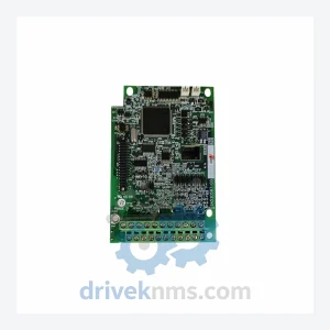
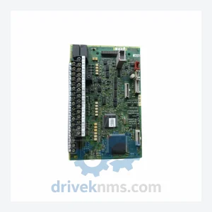
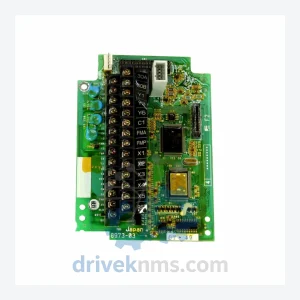
FUJI SA531121-03 E11-C4PCB Drive Board
FUJI SA531121-03 Series: Comprehensive Drive Board Range and Technical Overview The FUJI SA531121-03 series drive boards are core printed circuit…
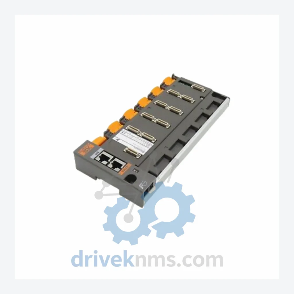
Model: NP1BS-06
Product Overview
Commercial availability is handled through direct RFQ, model verification and export-oriented follow-up rather than public cart checkout.
Datasheet Preview
Use attached product manuals when available. If the manual is not public yet, request the full file directly through RFQ.
Commercial Path
Product pages on DRIVEKNMS are designed to verify model, brand and series first, then move the buyer into one clean quotation path.
Technical Dossier
The Fuji Electric NP1B series — marketed under the MICREX-F platform — represents one of the most widely deployed modular PLC architectures in Asia-Pacific heavy industry. Installed across petrochemical complexes, nuclear auxiliary systems, steel rolling mills, and large-scale water treatment facilities, the NP1B backplane and its associated I/O and CPU modules have accumulated decades of field runtime in safety-critical environments. The series is characterized by a passive backplane architecture (base board) onto which CPU, I/O, communication, and power supply modules are inserted, enabling high-density control in compact panel footprints. The NP1BS-06 is a 6-slot base board that serves as the physical and electrical backbone of a single NP1B rack assembly, providing the inter-module bus, power distribution rails, and slot addressing logic for all inserted modules.
Fuji Electric introduced the MICREX-F / NP1 platform in the late 1980s as a successor to its earlier relay-logic and first-generation PLC systems. The NP1B designation identifies the base-board sub-family within the broader NP1 rack system. Early iterations used a proprietary parallel backplane bus operating at TTL logic levels, with slot counts of 4, 6, 8, and 12 positions (NP1BS-04, NP1BS-06, NP1BS-08, NP1BS-12). Through the 1990s, Fuji introduced enhanced CPU modules (NP1L-CPU series) with expanded program memory and floating-point support, while the base board hardware remained backward-compatible — a deliberate design choice that extended the installed base lifecycle well into the 2000s. By the mid-2000s, Fuji Electric began transitioning customers toward the MICREX-SX (SPH series) platform, which introduced a high-speed serial backplane and IEC 61131-3 programming compliance. As of 2026, the NP1B series is classified as End-of-Life (EOL) by Fuji Electric Japan; no new production orders are accepted. However, the installed base remains active in facilities where full DCS migration is cost-prohibitive, making third-party spare parts sourcing and lifecycle extension services the primary support pathway.
Base Boards (Backplane)
CPU Modules
Digital Input (DI) Modules
Digital Output (DO) Modules
Analog I/O Modules
Communication & Special Modules
Power Supply Modules
With Fuji Electric having formally discontinued the NP1B series, procurement teams at chemical plants, power utilities, and municipal water authorities face a narrowing supply window. DriveKNMS maintains a dedicated inventory of NP1B series modules — including base boards such as the NP1BS-06 — sourced through authorized surplus channels, factory-decommissioned equipment, and controlled refurbishment programs. All units are stored in ESD-safe, climate-controlled warehousing. For facilities operating under long-term maintenance contracts (LTMA) or asset integrity programs, DriveKNMS can provide scheduled delivery agreements to ensure continuity of spare parts availability through planned shutdown cycles. Emergency same-day quotation is available for critical production environments.
The NP1B base board (NP1BS-06 and related variants) presents specific test challenges due to its passive backplane design: the board itself carries no active logic, but its bus traces, slot connectors, and power rails must meet precise impedance and continuity specifications to ensure reliable inter-module communication. DriveKNMS applies a structured test protocol to all NP1B units: (1) visual inspection of PCB traces, connector pins, and solder joints under 10× magnification; (2) continuity and isolation testing of all backplane bus lines using a 4-wire Kelvin measurement method; (3) functional validation by inserting a known-good CPU and I/O module set and executing a cyclic scan test under rated load; (4) burn-in at 40°C ambient for 24 hours to screen latent component failures. CPU and I/O modules undergo additional firmware version verification and I/O point-level functional testing before release.
Related Paths
FUJI SA531121-03 Series: Comprehensive Drive Board Range and Technical Overview The FUJI SA531121-03 series drive boards are core printed circuit…
FUJI TEC-1VM Series: Comprehensive Module Range and Technical Overview The FUJI TEC-1VM series represents a core hardware platform deployed across…
FUJI NRC-2 SA516169-00 Circuit Board: Global Sourcing Strategy & Asset Return Value The FUJI NRC-2 SA516169-00 is a control circuit…