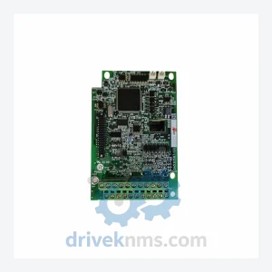
FUJI SA531121-03 E11-C4PCB Drive Board
FUJI SA531121-03 Series: Comprehensive Drive Board Range and Technical Overview The FUJI SA531121-03 series drive boards are core printed circuit…
Model: G11-PPCB-4-2.2 SA528530-05
Product Overview
Commercial availability is handled through direct RFQ, model verification and export-oriented follow-up rather than public cart checkout.
Datasheet Preview
Use attached product manuals when available. If the manual is not public yet, request the full file directly through RFQ.
Commercial Path
Product pages on DRIVEKNMS are designed to verify model, brand and series first, then move the buyer into one clean quotation path.
Technical Dossier
The FUJI G11 series represents one of FUJI Electric's core programmable controller and drive control platforms, with a documented installation base across heavy industrial sectors including petrochemical refining, nuclear power auxiliary systems, steel rolling mills, and large-scale water treatment facilities. The G11 architecture is deployed globally in applications requiring deterministic scan-cycle control, high-density I/O integration, and long-term field serviceability. Its modular backplane design allows incremental expansion without full system replacement, a critical factor for facilities operating under continuous-process constraints where downtime carries significant financial and safety implications. The G11-PPCB-4-2.2 SA528530-05 is a printed circuit board assembly within this platform, serving as a core processing or power interface sub-assembly depending on installation context.
FUJI Electric introduced the G11 platform as a successor to earlier G-series drive and control modules, consolidating communication, processing, and I/O functions into a standardized rack-mount form factor. Early G11 revisions used parallel backplane communication with proprietary FUJI bus protocols, limiting interoperability with third-party SCADA systems. Subsequent hardware revisions introduced RS-485 and later Profibus-DP interface options, expanding integration capability with Siemens and ABB distributed control environments. The SA5-series board assemblies (including SA528530-xx revision codes) represent a mid-to-late production run of the G11 platform, incorporating revised power regulation circuits and improved EMI shielding compared to earlier SA52xxxx-01/02 revisions. As of 2026, the G11 series is in the mature/end-of-life phase of its product lifecycle. FUJI Electric has transitioned its active development to the G1S and FRENIC series platforms. Replacement parts for G11 are no longer manufactured in volume; procurement relies on certified aftermarket suppliers and refurbished stock. Long-term maintenance support for G11 installations is a primary service requirement for facilities with 10–20 year operational horizons.
The following SKUs represent verified components within the FUJI G11 platform. Each entry reflects a distinct functional role within the system architecture.
G11-PPCB-4-2.2 SA528530-05: Main process PCB assembly, Rev.05, 4-axis control interface board
G11-PPCB-4-2.2 SA528530-04: Main process PCB assembly, Rev.04, prior revision of SA528530-05
G11-PPCB-4-2.2 SA528530-03: Main process PCB assembly, Rev.03, early production variant
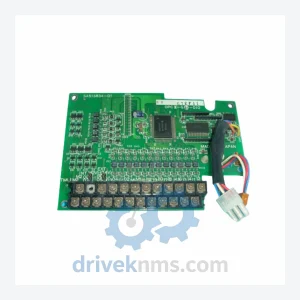
G11-CRB-1 SA528060-01: Control relay board, single-channel, auxiliary output interface
G11-CRB-2 SA528060-02: Control relay board, dual-channel, expanded auxiliary output
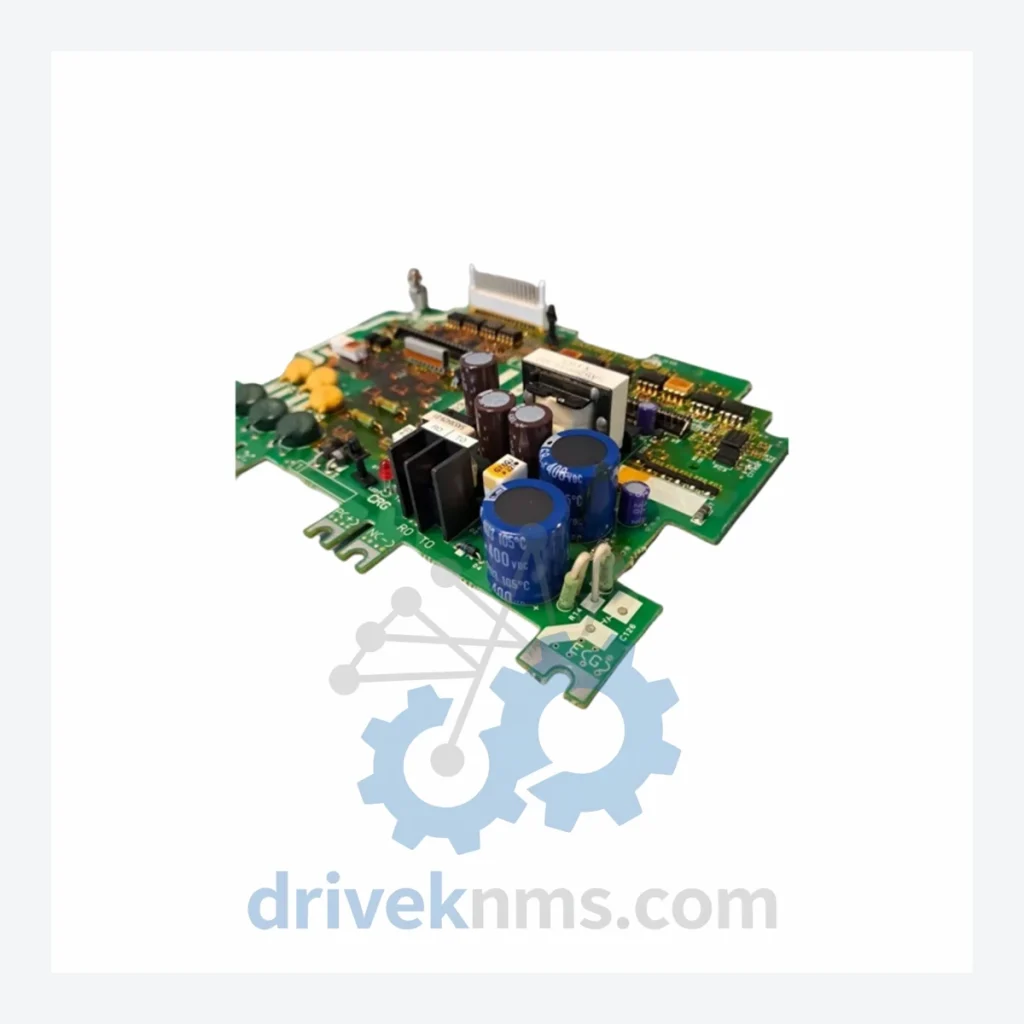
G11-PSB-1 SA527890-01: Power supply board, primary DC regulation module, 24VDC output
G11-PSB-2 SA527890-02: Power supply board, secondary regulation, redundant power path
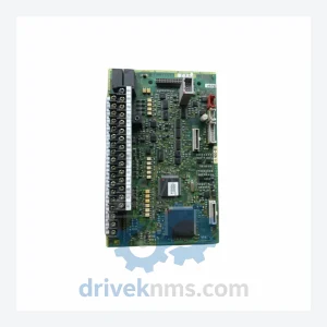
G11-IOB-16DI SA529100-01: Digital input board, 16-channel, 24VDC sink/source compatible
G11-IOB-16DO SA529100-02: Digital output board, 16-channel, transistor output, 0.5A per channel
G11-IOB-8AI SA529200-01: Analog input board, 8-channel, 4–20mA / 0–10V selectable
G11-IOB-4AO SA529200-02: Analog output board, 4-channel, 4–20mA isolated output
G11-COMM-PB SA530010-01: Profibus-DP communication adapter, slave mode, 12Mbps max
G11-COMM-485 SA530010-02: RS-485 serial communication board, Modbus RTU protocol
G11-CPU-A SA527500-01: Central processing unit board, primary scan controller, 32-bit
G11-CPU-B SA527500-02: Central processing unit board, extended memory variant, 64KB RAM
G11-BPB-8 SA526700-01: 8-slot backplane board, passive bus, rack-mount chassis interface
G11-BPB-16 SA526700-02: 16-slot backplane board, extended rack configuration
G11-FAN-ASY SA525300-01: Cooling fan assembly, rack-mount, thermal protection integrated
DriveKNMS maintains a dedicated inventory program for end-of-life FUJI G11 components. As FUJI Electric has discontinued active production of G11 series boards, the primary sourcing channels are certified refurbished units, decommissioned system pull-outs, and new-old-stock (NOS) from verified distributor closeouts. DriveKNMS applies a multi-source verification process to confirm part number authenticity before listing. For the SA528530-xx revision family specifically, revision-level traceability is maintained to prevent cross-revision substitution errors, which can cause incompatibility in backplane communication timing. Customers operating G11 systems in facilities with 5+ year remaining operational life are advised to establish a buffer stock of critical PCB assemblies, particularly CPU boards (SA527500-xx) and power supply boards (SA527890-xx), as these represent the highest failure-rate components in aging G11 installations. DriveKNMS can assist with lifecycle planning, bill-of-materials audits, and multi-unit procurement for scheduled maintenance windows.
FUJI G11 PCB assemblies undergo a structured inspection and functional test protocol at DriveKNMS prior to dispatch. Visual inspection covers solder joint integrity, capacitor condition (ESR measurement for electrolytic types), and connector pin alignment on backplane edge connectors. Functional testing for process boards such as the G11-PPCB-4-2.2 SA528530-05 includes powered bus communication verification using a G11-compatible rack test fixture, confirming correct data exchange across the backplane at rated clock speeds. Analog I/O boards are calibrated against a traceable reference standard to verify channel accuracy within ±0.1% of full scale. Communication adapter boards are tested for protocol compliance using a Profibus/Modbus analyzer. All units are assigned a test record with pass/fail data retained for 24 months. Units that do not meet functional thresholds are quarantined and not offered for sale.
Related Paths
FUJI SA531121-03 Series: Comprehensive Drive Board Range and Technical Overview The FUJI SA531121-03 series drive boards are core printed circuit…
FUJI TEC-1VM Series: Comprehensive Module Range and Technical Overview The FUJI TEC-1VM series represents a core hardware platform deployed across…
Fuji SA513834-01 Control Board – Obsolete FUJI Series Spare Part When a control board fails in a legacy Fuji Electric…