A pressure-controlled pump that stops without a drive fault may be doing exactly what its application settings require. If an Altivar 61 uses PID sleep and wake-up functions, the next start depends on the selected restart criterion and the feedback signal, not simply on the presence of a run request. Replacing the drive before documenting that behavior can reproduce the same complaint on new hardware.
The practical question is whether the pump is asleep, inhibited, tripped or receiving an incorrect process value. Those states require different evidence. This evergreen guide focuses on preserving the sleep and wake-up behavior during diagnosis and spare preparation; it does not prescribe operating thresholds for an unknown pumping system.
Begin with the stopped state, not a parameter change
Capture the displayed operating state, active faults, selected control mode, run demand, PID reference and PID feedback. Record when the pump stopped and what the process did afterward. A pressure trace without the corresponding drive state can make a deliberate low-demand stop look like an intermittent failure.
Also identify whether the PID controller resides in the drive, a PLC or a dedicated option. A plant drawing that simply says pressure control is not sufficient. An external controller may remove a command independently of the drive’s internal sleep function. A water application option may introduce its own sequence. Establish the control ownership before comparing parameters.
When documenting an installed unit, the ATV61HU40N4 product reference can anchor a sourcing inquiry to a specific catalog number. Preserve the actual nameplate, firmware and fitted options alongside it. A matching family name does not prove an identical application configuration.
Different wake-up criteria answer different questions
Schneider’s ATV61 and ATV71 wake-up guidance distinguishes a speed-related sleep offset, a PID error criterion and a feedback threshold. Its examples explain the concepts; they are not universal pump settings. A frequency offset and a pressure-related value cannot be compared as though they were the same unit.
For a speed-related criterion, the evidence concerns the relevant reference and its relationship to low speed. For an error criterion, examine the difference between the PID target and feedback. For a feedback threshold, establish what measured value is being compared. Confirm which method is actually configured, rather than assuming the operator’s phrase restart pressure identifies the implemented function.
The manufacturer’s basic PID setup guidance is a useful companion for identifying the reference and feedback paths. Application-specific acceptance must still account for the pump, pressure vessel, minimum-flow requirements, process tolerances and protective functions.
Feedback scaling can hide the real demand
A transmitter replacement or range change can leave a plausible-looking number with the wrong meaning. Record its measurement range, signal type and configured scaling. Compare the control-system value with an appropriate independent process indication under an approved test plan. Do not assume that a nonzero analog value proves an accurate pressure measurement.
Timing matters too. Record when demand changes, when the feedback changes and when the drive changes state. A restart delay may be intentional; a frozen value may originate upstream of the drive. A trend should identify units, sampling interval and observation time so another engineer can interpret it without reconstructing the entire visit.
Do not lower a wake-up threshold merely to force a visible start. That can conceal a feedback problem or introduce excessive cycling. Equally, do not disable a permissive to isolate the sleep logic. Pump protection and personnel safety remain separate requirements even when the immediate complaint is low delivery pressure.
Prepare a spare for the whole operating cycle
For another installed frame, such as the ATV61HD37N4 drive reference, build its own identity and configuration record. These two catalog references are not presented as interchangeable. Motor duty, supply, enclosure, options and approved application settings must be matched to the specific installation.
Archive the readable configuration with its date and software version. Keep a separate description of the expected operating sequence. A parameter file may be technically readable while failing to explain why a pump should remain stopped at one pressure and restart at another. That explanation belongs to the plant’s controlled engineering record.
The acceptance plan should cover stable normal demand, entry into the intended low-demand state and recovery when demand returns. Include the response to invalid feedback and relevant stop conditions. Tests involving process operation require plant authorization and qualified supervision; they should not be improvised at a receiving desk.
Agree what a supplier can demonstrate before shipment and what must be demonstrated on site. Hardware inspection and a basic functional test do not recreate the installed hydraulic system. A clear division of acceptance responsibilities is more useful than a broad statement that a drive has been tested.
Frequently asked questions
Does sleep mean the drive has failed?
No. Sleep can be a normal low-demand operating state. Confirm the actual displayed state and the configured application before deciding. A fault, missing permissive or loss of command may produce a similar stopped pump but has a different cause and recovery process.
Can a copied parameter file prove correct wake-up?
No. The file needs to match the hardware, firmware, options and plant application. Correct feedback scaling and observed process behavior also matter. Preserve the file as evidence, then verify the intended sequence through the approved commissioning and acceptance process.
Should a replacement drive be tested only at full demand?
That leaves the reported behavior untested. A pump can run satisfactorily at high demand yet fail to enter or leave its intended low-demand state. Include the relevant operating transitions and protective responses in a supervised test plan appropriate to the installation.
What should a maintenance team send for spare identification?
Send the full drive label, motor data, fitted-option details and a concise description of the observed stop and restart sequence. DriveKNMS can use those records to clarify the requested hardware and supplied scope. Keep process settings under the responsible engineer’s control rather than treating a quotation as commissioning approval.
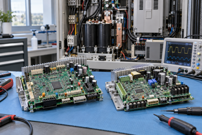
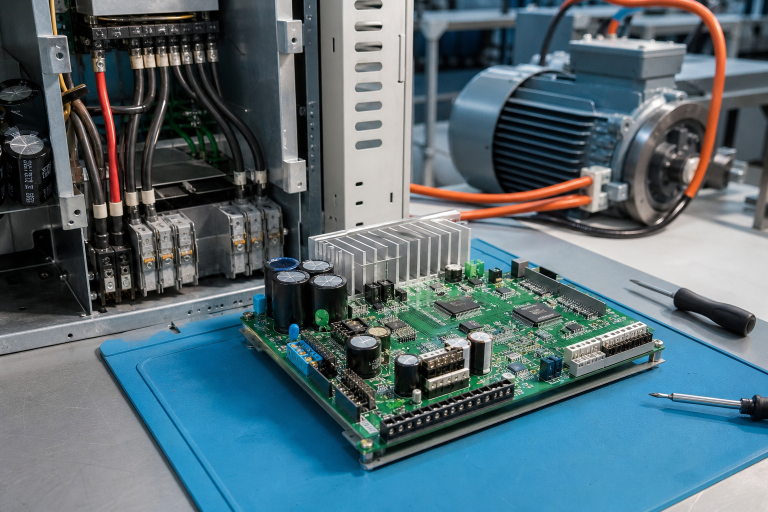
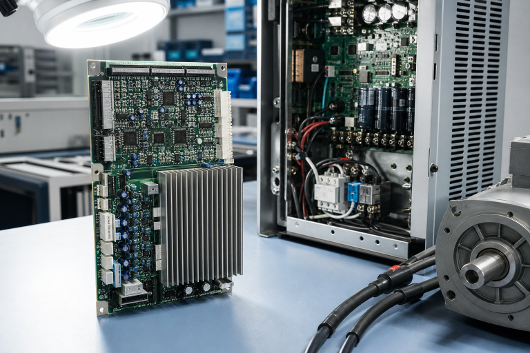
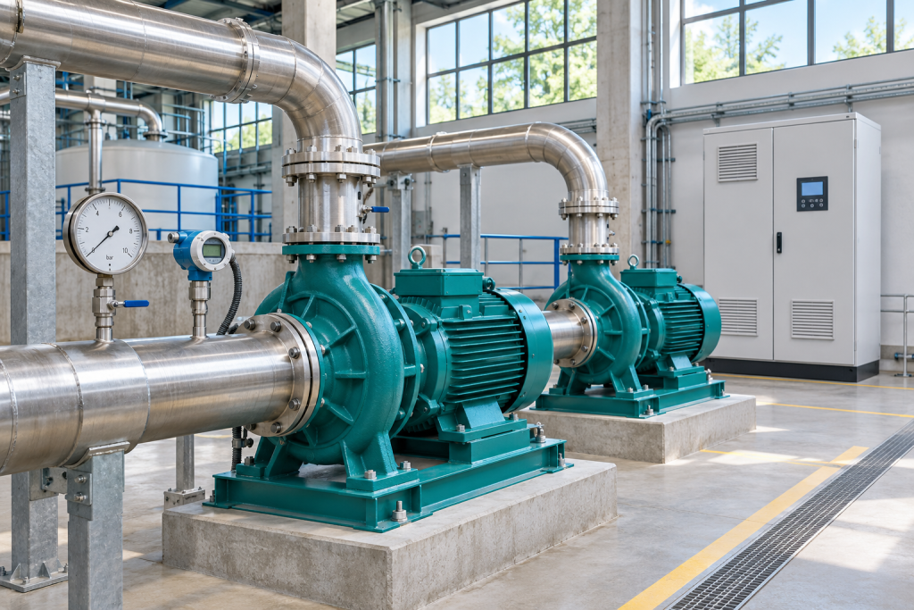
Image: AI-generated editorial illustration, not an exact product photograph or installation reference.
© 2026 DriveKNMS. All rights reserved. Official Website: https://driveknms.com Inquiry: sale@driveknms.com | WhatsApp/Tel: +86 18359293191