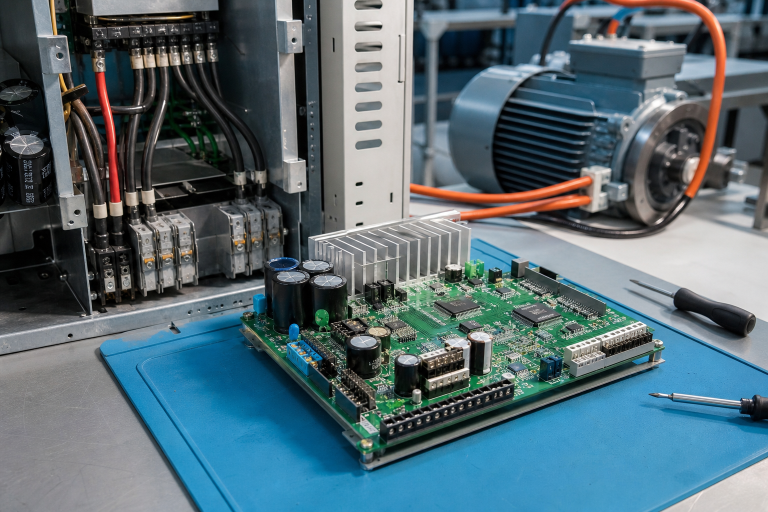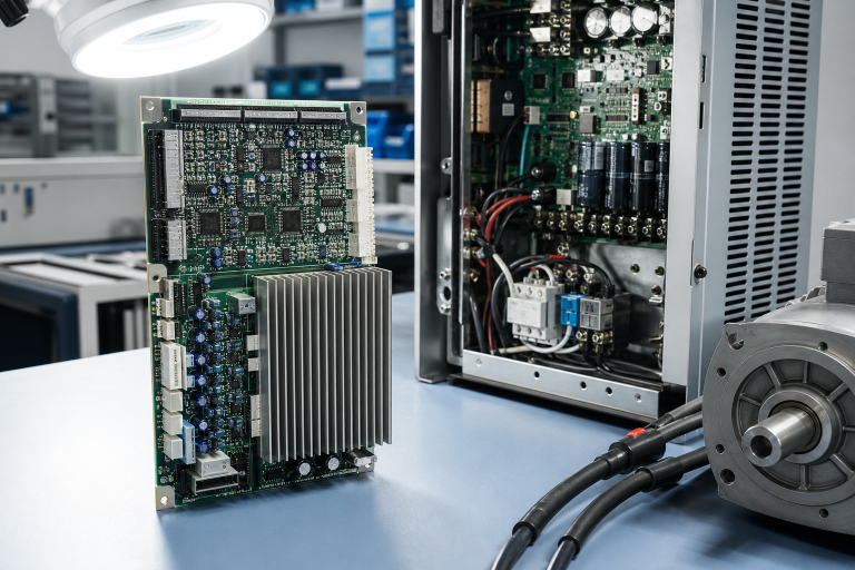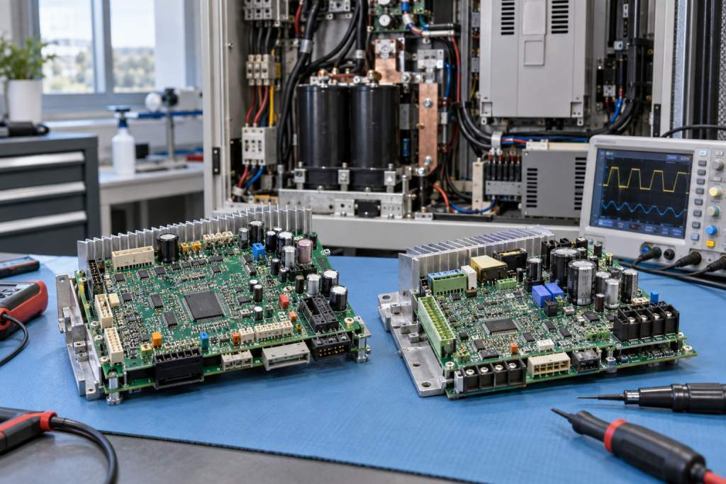
When a production drive fails, the fastest answer is often “send the control board.” That answer can be wrong. A DC bus problem, braking circuit, gate-drive fault, cooling failure or encoder issue can produce the same trip code and destroy a replacement board. The cost is not only the part. It is the second outage, the lost fault evidence and the time spent proving that the first diagnosis was incomplete.
Legacy drives deserve a more deliberate method because their documentation, boards and firmware are often harder to replace. The plant may be planning a larger motion upgrade, but the line still needs a controlled recovery today. Start by proving the energy path, then match the board to the actual drive and test scope.
Capture the drive state safely
Record drive model, rating, input voltage, motor data, control mode, feedback type, firmware, keypad messages and the exact trip timestamp. Photograph the nameplate, board labels, terminal positions and cooling path. Preserve parameter backups through the authorized procedure. Note whether the trip happened at start, acceleration, regeneration, steady speed or stop.
Never open a drive until the site’s isolation and discharge procedure is complete. Verify the DC bus is at a safe level with an approved instrument. A board that looks burned may be the victim of an upstream supply event, and a board that looks clean may contain a failed power device. Safety and evidence come before parts selection.
Separate DC bus, inverter and feedback causes
Check incoming phases, fuses, contactors, pre-charge, bus voltage, braking resistor, cooling fan and grounding. Compare the measured behavior with the drive manual and the plant’s safe test procedure. If the fault appears only under load, check the motor, cable insulation and mechanical load before condemning the inverter board.
The Yaskawa YPHT11014-1A drive control board must be matched to the exact drive family, board revision, connectors and application. Ask whether the board has been tested in a representative chassis or only powered on a bench. For obsolete stock, require a condition statement and a defined return or exchange process.
The Fuji EP-3364B-CA-Z2 inverter control board should be checked against the FRENIC series, gate-drive arrangement, firmware context and connector map. Do not approve a visually similar EP-series board without confirming the installed drive and the test boundaries.
Make the replacement reversible
Before the shutdown, assign who will isolate energy, who will install the board, who will restore parameters and who will authorize the first run. Label cables and connector positions. Record the removed board’s serial number and fault condition. If a spare is sent to an outside test house, keep the original failure evidence and photos with the shipment.
After installation, verify power-up diagnostics, parameter load, motor direction, encoder feedback, current balance, acceleration, stopping, braking and interlocks. Run the motor under an approved no-load or controlled load condition before returning to production. Confirm that the original fault does not reappear at the same speed or torque point.
If the drive is a bridge asset while the line moves to a newer platform, record the retirement milestone and remaining critical spares. The procurement decision should balance repair availability, board test quality, lead time and the production consequence of another failure. A small number of tested boards can be more useful than a large number of unidentified cards.
Use the repair report to improve the next RFQ. Include the exact trip, measured bus values, board revision, motor information and what the supplier tested. This reduces back-and-forth and helps the sourcing team reject a tempting but unverified substitute.
Keep one known-good parameter file with the drive identification, but do not overwrite a production backup with a file from a different rating or motor. Record acceleration and deceleration limits, braking method, encoder type and any special application cards. A board replacement is safer when the recovery package tells the technician what must remain unchanged.
During the first run, compare current, speed feedback, temperature and acoustic behavior with the pre-fault baseline. If the replacement board survives only at light load, stop the test and investigate the upstream condition. A short successful jog is not evidence that the drive is ready for a full production cycle.
Keep the drive cabinet thermal condition in the record as well. A board that fails after the cabinet warms up points to a different investigation from a board that fails at power-up.
Questions maintenance teams usually ask
Can a DC bus trip prove that the inverter board failed?
No. Check supply, pre-charge, braking, motor cable, mechanical load, cooling and feedback before blaming the board.
Is a powered-up legacy board ready for service?
Not by itself. Confirm diagnostics, connectors, revision, parameter context and representative load testing, and state what was not tested.
Should the old board be discarded after the swap?
Keep it tagged until the root-cause review is closed. It may contain evidence or remain repairable for a controlled exchange.
What belongs in a drive-board RFQ?
Include drive model, board number and revision, motor data, trip code, measured conditions, photos, quantity, condition expectation and required date.
Source the board only after proving the fault path
Legacy drive recovery becomes faster when diagnosis and procurement share the same evidence. A safe bus check, exact board match and transparent test scope protect the line while a modernization project is being planned.
Send the drive nameplate, board label, fault history and timing requirement to driveknms. We can help validate the spare and prepare a practical quotation.
© 2026 DriveKNMS. All rights reserved. Official Website: https://driveknms.com Inquiry: sale@driveknms.com | WhatsApp/Tel: +86 18359293191