
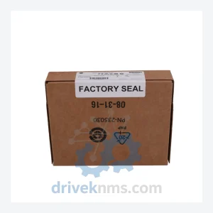
Allen-Bradley 1756-OB16E Digital Output Module – ControlLogix 16-Point Spare Part
Allen-Bradley 1756-OB16E is listed for ControlLogix RFQ review. Confirm quantity, condition and destination before quotation.
RFQ-ready industrial model
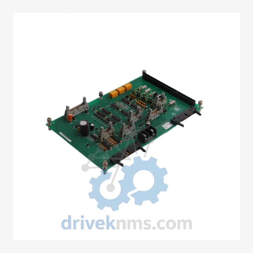
Model: 170947/170948 129708-02 M003325108
Product Overview
Commercial availability is handled through direct RFQ, model verification and export-oriented follow-up rather than public cart checkout.
Datasheet Preview
Use attached product manuals when available. If the manual is not public yet, request the full file directly through RFQ.
Commercial Path
Product pages on DRIVEKNMS are designed to verify model, brand and series first, then move the buyer into one clean quotation path.
Technical Dossier
The Allen-Bradley 170947/170948 series Power Stage Interface Boards are critical sub-assemblies within Rockwell Automation's drive and motion control platforms, including the 1336 PLUS, 1336 PLUS II, and related PowerFlex predecessor drive families. These boards serve as the electrical and signal interface between the control logic section and the IGBT/transistor power stage, managing gate drive signals, fault feedback, and DC bus sensing. Installed across global heavy industry — including petrochemical refineries, nuclear auxiliary systems, offshore platforms, and continuous process plants — these interface boards are subject to long operational cycles and are frequently required as maintenance spares decades after original commissioning. The 129708-02 revision designation and M003325108 manufacturing reference identify a specific board revision used in mid-to-high horsepower drive frames.
The following SKUs represent the documented range of power stage interface boards, gate driver boards, and associated sub-assemblies used across the 1336 PLUS / PLUS II drive family. All models listed are confirmed Allen-Bradley / Rockwell Automation part numbers associated with this platform.
170947/170948 129708-02 M003325108: Power stage interface board, mid-frame, rev -02, gate drive and fault feedback
170947: Base power stage interface board assembly, early revision, 1336 PLUS frame C/D
170948: Revised power stage interface board, updated isolation circuit, 1336 PLUS frame C/D
129708-01: PCB sub-assembly, power stage interface, revision -01, predecessor to -02 ECO
129708-02: PCB sub-assembly, power stage interface, revision -02, updated fault latch circuit
80026-088-51: Gate driver board, 1336 PLUS II, upper/lower IGBT drive, frame D
80026-088-52: Gate driver board, 1336 PLUS II, revised deadtime control, frame D/E
80026-088-01: Gate driver board, 1336 PLUS, early production, frame B/C
74101-716-51: Power interface board, 1336 PLUS II, frame E, high-horsepower variant
74101-716-52: Power interface board, revised snubber network, frame E/F
80026-089-01: Precharge interface board, 1336 PLUS, DC bus precharge control signal interface
80026-089-02: Precharge interface board, revised inrush timing circuit, 1336 PLUS II
74101-715-51: Control-to-power interface ribbon assembly, 1336 PLUS II, frame D
80190-750-01: Fiber optic gate drive interface board, 1336 PLUS II, frame F and above
80190-750-02: Fiber optic gate drive interface board, revised receiver sensitivity, frame F/G
74101-718-51: Current feedback interface board, hall-effect sensor signal conditioning, frame E
80026-090-01: Thermistor and thermal protection interface board, 1336 PLUS, all frames
129707-01: Companion control stage interface board, pairs with 129708-02 in frame C/D assemblies
Power stage interface boards in the 170947/170948 family present specific test challenges due to their role as the signal boundary between low-voltage control logic (typically 5–15 VDC logic levels) and high-voltage gate drive outputs (15–20 VDC gate signals referenced to floating emitter potentials). DriveKNMS applies the following test protocol to all units in this family: (1) Visual inspection under 10× magnification for PCB delamination, solder joint fatigue, and component date code verification. (2) Isolation resistance test: >100 MΩ at 500 VDC between control-side common and power-side gate drive outputs. (3) Functional gate drive signal verification using a dedicated 1336-compatible drive test fixture, confirming correct PWM signal propagation, deadtime insertion, and fault latch behavior. (4) DC bus voltage divider accuracy check: output voltage ratio verified within ±1% of nominal specification. (5) Thermal cycling: boards subjected to 10 cycles between 0°C and 70°C with functional verification at temperature extremes. Units that fail any stage are quarantined and not returned to inventory.
Continue The Model Path
Move from this exact model into the matching system hub, brand archive, model-family archive or lifecycle sourcing route before sending a final RFQ list.
Related Paths
Allen-Bradley 1756-OB16E is listed for ControlLogix RFQ review. Confirm quantity, condition and destination before quotation.
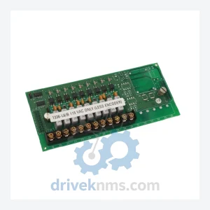
Allen-Bradley 1336-L6/B is listed for Controller Cards RFQ review. Confirm quantity, condition and destination before quotation.
Allen-Bradley 1786-BNC is listed for Controller Cards RFQ review. Confirm quantity, condition and destination before quotation.