
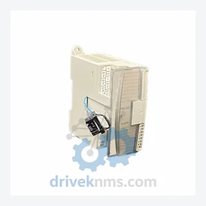
Allen-Bradley 1762-OA8 Digital Output Module – Obsolete MicroLogix Spare Part
Allen-Bradley 1762-OA8 is listed for MicroLogix RFQ review. Confirm quantity, condition and destination before quotation.
RFQ-ready industrial model
Model: 1763-L16BBB
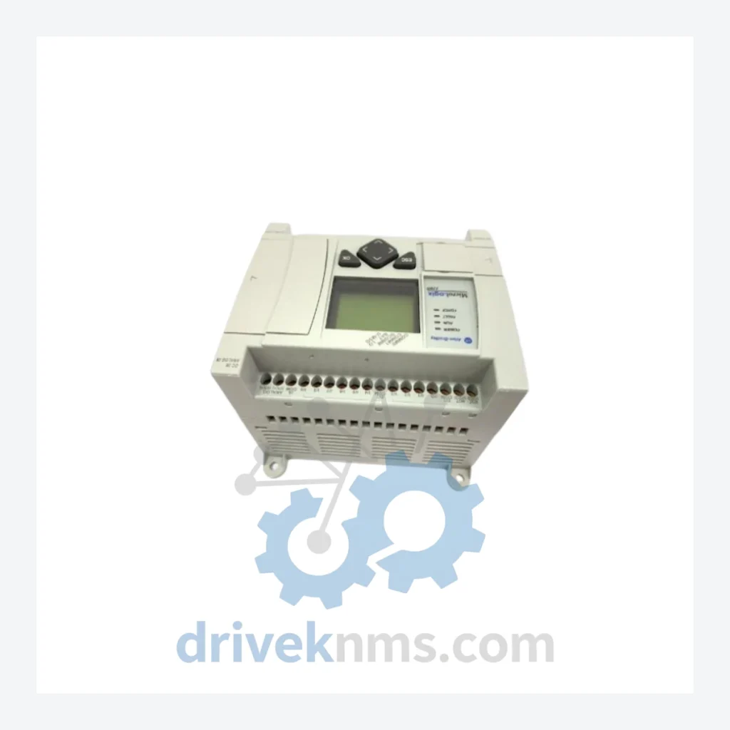
Product Overview
Commercial availability is handled through direct RFQ, model verification and export-oriented follow-up rather than public cart checkout.
Datasheet Preview
Use attached product manuals when available. If the manual is not public yet, request the full file directly through RFQ.
Commercial Path
Product pages on DRIVEKNMS are designed to verify model, brand and series first, then move the buyer into one clean quotation path.
Technical Dossier
The Allen-Bradley MicroLogix 1100 series (catalog prefix: 1763) is a compact, fixed-I/O programmable logic controller platform developed by Rockwell Automation. It is deployed across a broad range of continuous and discrete process industries, including petrochemical refining, water/wastewater treatment, pharmaceutical manufacturing, and power generation auxiliary systems. Its embedded 10/100 Ethernet port (EtherNet/IP), onboard LCD operator interface, and support for up to 144 I/O points via expansion make it one of the most widely installed small PLC platforms in global heavy industry. Installed base estimates place the MicroLogix 1100 in active service at tens of thousands of sites across North America, Europe, and Asia-Pacific, with a significant proportion of units operating beyond their original design lifecycle in legacy control panels.
The MicroLogix 1100 was introduced by Rockwell Automation as a successor to the MicroLogix 1000 (1761 series), addressing the demand for integrated Ethernet connectivity in a sub-compact form factor. The original MicroLogix 1000 lacked native Ethernet and required external communication adapters for network integration. The 1100 resolved this by embedding an EtherNet/IP port directly on the base unit, enabling direct MSG instruction communication with other Logix controllers and SCADA systems without additional hardware.
The architecture is built around a fixed-I/O base unit with an integrated power supply, CPU, and I/O in a single housing. Expansion is achieved via the 1762 MicroLogix Expansion I/O modules, which connect to the right side of the base unit via a proprietary backplane bus. The controller supports up to 7 expansion modules, extending the maximum I/O count to 144 discrete or analog points. Programming is performed exclusively via RSLogix 500 (or Studio 5000 Logix Designer for migration projects), using Ladder Diagram (LD) as the primary language, with limited Function Block Diagram (FBD) support in later firmware revisions.
Rockwell Automation has classified the MicroLogix 1100 as a mature product. While not formally discontinued as of this writing, the recommended migration path for new designs is the Micro820 (2080 series) or Micro850 (2080 series) controllers, which offer expanded memory, IEC 61131-3 multi-language support, and plug-in module architecture. For existing installations, Rockwell continues to provide spare parts and firmware support, but feature development has ceased.
The following SKUs represent the verified MicroLogix 1100 base unit catalog (1763 series) and directly associated 1762 expansion I/O modules. All models listed are confirmed Rockwell Automation catalog numbers.
Base Controllers (1763 Series)
1762 Expansion I/O Modules (MicroLogix Expansion)
MicroLogix 1100 base units and 1762 expansion modules are tested against a defined acceptance protocol prior to dispatch. The test procedure addresses the specific failure modes documented in Rockwell Automation field service bulletins for this platform:
Continue The Model Path
Move from this exact model into the matching system hub, brand archive, model-family archive or lifecycle sourcing route before sending a final RFQ list.
Related Paths
Allen-Bradley 1762-OA8 is listed for MicroLogix RFQ review. Confirm quantity, condition and destination before quotation.
Allen-Bradley 1769-L23-QBFC1B is listed for MicroLogix RFQ review. Confirm quantity, condition and destination before quotation.
Allen-Bradley 1766-L32AWA is listed for MicroLogix RFQ review. Confirm quantity, condition and destination before quotation.