
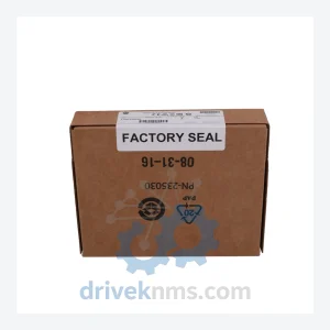
Allen-Bradley 1756-OB16E Digital Output Module – ControlLogix 16-Point Spare Part
Allen-Bradley 1756-OB16E is listed for ControlLogix RFQ review. Confirm quantity, condition and destination before quotation.
RFQ-ready industrial model
Model: A74104-241-53
Product Overview
Commercial availability is handled through direct RFQ, model verification and export-oriented follow-up rather than public cart checkout.
Datasheet Preview
Use attached product manuals when available. If the manual is not public yet, request the full file directly through RFQ.
Commercial Path
Product pages on DRIVEKNMS are designed to verify model, brand and series first, then move the buyer into one clean quotation path.
Technical Dossier
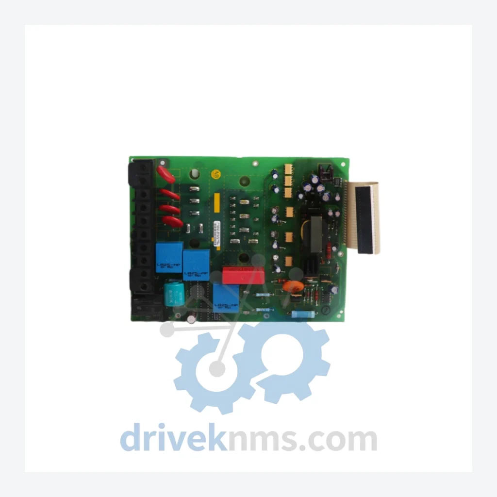
The A74104 control board lineage originates from Allen-Bradley's analog and early digital DC drive platforms, specifically the 1395 and 1391 series DC drives, as well as select 1336 AC drive variants. Early-generation A74104 boards utilized discrete analog signal processing with hardwired potentiometer-based speed and current reference circuits. Mid-generation revisions introduced hybrid analog-digital architectures, incorporating microprocessor-based fault logging while retaining analog firing circuits for SCR/thyristor gate control.
Later revisions transitioned to fully digital control loops with EEPROM-based parameter storage, enabling non-volatile retention of drive tuning data across power cycles. Compatibility between board revisions is not universal: backplane connector pinouts, firmware revision dependencies, and gate driver voltage levels vary across sub-variants. Maintenance engineers must cross-reference the drive's nameplate catalog number against the specific A74104 sub-variant (e.g., -241-53, -241-54) before substitution. Modern replacement pathways include migration to the Allen-Bradley PowerFlex 523, 525, or 755 platforms, though these require full drive chassis replacement and parameter re-commissioning.
The following SKUs represent verified components within the Allen-Bradley A74104 control board family and associated drive control assemblies. Each entry reflects a distinct functional role within the drive system:
A74104-241-53: Main SCR firing control board, 1395 DC drive, analog/digital hybrid architecture
A74104-241-54: Revised firing control board, updated gate driver circuit, 1395 DC drive
A74104-241-55: Enhanced noise immunity variant, shielded signal traces, 1395 DC drive
A74104-ES001: Encoder signal conditioning board, quadrature input, 1395 series
A74104-ES002: Dual-channel encoder interface, differential line driver compatible
A74104-PS001: Isolated power supply board, ±15 VDC analog rail, 1395 drive chassis
A74104-PS002: Regulated 24 VDC logic supply board, overcurrent protected
A74104-REG001: Current regulator board, PI loop control, armature current feedback
A74104-REG002: Speed regulator board, tachometer feedback input, analog trim
A74104-FBK001: Armature voltage feedback board, isolated differential measurement
A74104-FBK002: Field current feedback board, shunt-based sensing interface
A74104-COM001: Serial communications adapter board, RS-232/RS-485 selectable
A74104-COM002: DH+ communications interface board, 1395 drive remote I/O link
A74104-IO001: Discrete I/O expansion board, 8 DI / 4 DO, 24 VDC logic
A74104-IO002: Analog I/O board, 4–20 mA / 0–10 VDC input/output channels
A74104-GD001: Gate driver amplifier board, SCR pulse transformer output stage
A74104-GD002: Dual-bridge gate driver board, regenerative drive configuration
A74104-DIAG001: Diagnostic and fault display board, LED fault code annunciator
A74104 control boards undergo a structured multi-stage inspection and functional verification process at DriveKNMS facilities. Visual inspection covers solder joint integrity, capacitor condition (ESR measurement for electrolytic types), trace continuity, and component identification against original bill-of-materials references. Functional testing is performed using dedicated drive emulation test rigs that replicate the 1395 drive backplane signal environment, including armature feedback simulation, tachometer signal injection, and gate pulse output verification under load-equivalent conditions.
Continue The Model Path
Move from this exact model into the matching system hub, brand archive, model-family archive or lifecycle sourcing route before sending a final RFQ list.
Related Paths
Allen-Bradley 1756-OB16E is listed for ControlLogix RFQ review. Confirm quantity, condition and destination before quotation.
Allen-Bradley 1336-L6/B is listed for Controller Cards RFQ review. Confirm quantity, condition and destination before quotation.
Allen-Bradley 1786-BNC is listed for Controller Cards RFQ review. Confirm quantity, condition and destination before quotation.