
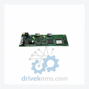
ABB NAMC-11C
ABB NAMC-11C is listed for Controller Cards RFQ review. Confirm quantity, condition and destination before quotation.
RFQ-ready industrial model
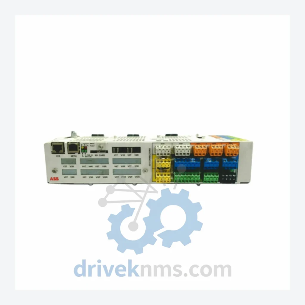
Model: BCU-12C 3AUA0000110429
Product Overview
Commercial availability is handled through direct RFQ, model verification and export-oriented follow-up rather than public cart checkout.
Datasheet Preview
Use attached product manuals when available. If the manual is not public yet, request the full file directly through RFQ.
Commercial Path
Product pages on DRIVEKNMS are designed to verify model, brand and series first, then move the buyer into one clean quotation path.
Technical Dossier
The ABB BCU (Brake Control Unit / Drive Control Unit) series represents a core control architecture deployed across ABB's ACS800, ACS880, and ACS580 frequency converter platforms. These control boards are installed in heavy industrial environments including petrochemical refineries, nuclear auxiliary systems, offshore platforms, pulp and paper mills, and large-scale HVAC infrastructure. The BCU-12C (part number 3AUA0000110429) is a control board designed for multi-drive and single-drive configurations, providing the primary processing and I/O interface layer between the drive hardware and the plant control network. Its deployment footprint spans installations across Europe, Asia-Pacific, and the Middle East, where ABB drives are the dominant variable speed drive (VSD) platform in process-critical applications.
ABB's drive control board architecture evolved through several distinct generations. Early ACS800 platforms (introduced late 1990s) used the RMIO and RDCO board families for control and fieldbus interfacing. As drive power density increased and multi-drive cabinet architectures became standard in the 2000s, ABB introduced the BCU (Board Control Unit) platform to centralize control logic across multiple inverter modules sharing a common DC bus.
The BCU-12C represents the second-generation BCU architecture, optimized for ACS800-104 and ACS800-304 multi-drive systems. It introduced expanded memory, improved real-time processing for torque control loops, and native support for DDCS (Distributed Drive Control System) fiber-optic communication. Compatibility considerations are significant: BCU-12C boards are not directly interchangeable with first-generation BCU-02 or BCU-02C boards without firmware alignment. The transition to the ACS880 platform introduced the ZCU (Zone Control Unit) and BCU-22 families, which use a different backplane connector standard and are not backward-compatible with BCU-12C hardware slots.
The following SKUs represent the verified BCU and associated control board range for ABB ACS800/ACS880 multi-drive and single-drive platforms. Each entry reflects a distinct hardware revision or functional variant:
3AUA0000110429 (BCU-12C): Primary control board for ACS800 multi-drive; DDCS fiber I/O, 2 AI, 3 DI, 2 DO
3AUA0000025701 (BCU-02): First-generation BCU; ACS800 single/multi-drive base control
3AUA0000025702 (BCU-02C): BCU-02 with extended I/O; 4 AI, 6 DI, 3 DO configuration
3AUA0000110430 (BCU-12): BCU-12C variant without conformal coating; standard industrial environments
3AUA0000025750 (RDCU-02C): Remote drive control unit; panel-mount variant of BCU-02C
3AUA0000025751 (RDCU-12C): Remote drive control unit; panel-mount variant of BCU-12C
3AUA0000025800 (RMIO-02): Motor control I/O board; analog and digital I/O expansion for ACS800
3AUA0000025801 (RMIO-11): RMIO variant with encoder interface; closed-loop speed control
3AUA0000025810 (RDIO-01): Digital I/O extension module; 8 DI / 6 DO for ACS800 control section
3AUA0000025820 (RAIO-01): Analog I/O extension; 4 AI / 2 AO for process variable interfacing
3AUA0000025830 (RDCO-01): DDCS fiber-optic communication adapter; CH0 master link
3AUA0000025831 (RDCO-02): DDCS adapter; CH1/CH2 expansion for multi-drive ring topology
3AUA0000025840 (RPBA-01): PROFIBUS-DP adapter module; DP-V1 slave for ACS800 fieldbus integration
3AUA0000025841 (RCAN-01): CANopen adapter; DS402 drive profile for motion control networks
3AUA0000025850 (RETA-01): Ethernet adapter; Modbus TCP / EtherNet/IP dual-protocol for ACS800
3AUA0000025860 (RDNA-01): DeviceNet adapter; Group 2 slave for ACS800 in automotive/assembly lines
3AUA0000025870 (RLON-01): LonWorks adapter; HVAC building automation integration for ACS800
3AUA0000025880 (RMBA-01): Modbus RTU adapter; RS-485 serial fieldbus for legacy SCADA systems
For installations where ACS800 drives remain in service beyond their original design life — common in refineries and power generation facilities with 20–30 year asset cycles — DriveKNMS provides lifecycle extension support including: verified replacement boards with matched firmware revisions, cross-reference validation against installed drive configuration files (*.dcp), and exchange programs for boards with repairable fault conditions (blown fuses, failed EEPROM, damaged fiber ports).
BCU-12C boards present specific test challenges due to their integrated DDCS fiber-optic transceivers, dual-port FLASH memory, and real-time DSP core. DriveKNMS applies the following test protocol to all BCU-12C units prior to dispatch:
1. Visual inspection: PCB layer delamination, capacitor ESR check, connector pin integrity on X1/X2/X3 backplane headers.
2. Powered bench test: Board is installed in an ACS800 test chassis. Drive firmware is loaded and parameter set 99 (motor data) is initialized. Fault log is cleared and drive is cycled through START/STOP sequences under no-load conditions.
3. DDCS communication verification: Fiber-optic CH0 link is tested at 4 Mbit/s using an RDCO-02 loopback adapter. Packet error rate must be 0% over a 10-minute continuous test window.
4. I/O functional test: All analog inputs (0–10 V and 4–20 mA), digital inputs (24 VDC), and relay outputs are verified against the BCU-12C hardware manual (3AUA0000025999).
5. Thermal cycling: Board is subjected to 0°C to 55°C thermal cycle (2 cycles) to identify cold-solder joint failures not visible under static conditions.
6. Final firmware check: Installed firmware version is documented and matched to the customer's drive system version where specified.
Continue The Model Path
Move from this exact model into the matching system hub, brand archive, model-family archive or lifecycle sourcing route before sending a final RFQ list.
Related Paths
ABB NAMC-11C is listed for Controller Cards RFQ review. Confirm quantity, condition and destination before quotation.

ABB LL02 is listed for Controller Cards RFQ review. Confirm quantity, condition and destination before quotation.
ABB LZ02 is listed for H&B Contronic LZ Series RFQ review. Confirm quantity, condition and destination before quotation.