Technical Dossier
Product Details And Specifications
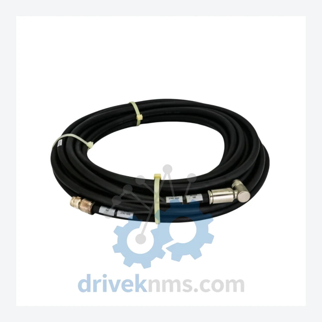
Applied Materials 0150-10613 RF Cable Assembly – Obsolete AMAT Spare Part
DriveKNMS maintains RFQ-reviewed sourcing status of the AMAT 0150-10613 / 20360207 / 20704A-25352 coaxial RF cable assembly. This is not a catalog listing. If it is on this page, it is in our warehouse.
RFQ support for obsolete parts: Send the model number, required quantity and destination so DriveKNMS can confirm sourcing options before quotation.
Technical Specifications
Note: Electrical parameters such as impedance rating, connector type, and cable length are confirmed at time of order. We do not publish unverified specifications.
Solving the Discontinued Hardware Crisis
Applied Materials tools built on DPA-based RF architectures represent a generation of semiconductor capital equipment that was engineered for 10–15 year operational lifespans. Many of these tools are now 20+ years into service. The RF subsystem — particularly the cable assemblies connecting the generator to the power amplifier — is a wear item subject to dielectric degradation, connector oxidation, and shield braid fatigue over time.
Facilities that have extended the life of their AMAT tools by 5–10 years beyond OEM support windows consistently share one operational discipline: they maintain a minimum of one spare for every high-wear, single-point-of-failure component in the RF chain. The 0150-10613 assembly is precisely that type of component. Its failure mode is not gradual — RF cable assemblies in high-power environments tend to fail abruptly, without warning, under thermal or mechanical stress.
Condition & Reliability Assurance
Every 0150-10613 assembly that leaves our facility passes a structured 5-step inspection protocol before it is offered for sale:
- Step 1 – Visual and Mechanical Inspection: Full external inspection of cable jacket, connector bodies, and strain relief. Any unit showing jacket cracking, connector deformation, or mechanical damage is rejected.
- Step 2 – Connector Pin and Shield Integrity: Center conductor and outer shield continuity verified. Pin corrosion, oxidation, and contact recession are checked under magnification. Corroded contacts are not reconditioned — the unit is rejected.
- Step 3 – Dielectric Integrity Check: Insulation resistance between center conductor and shield is measured. Units showing degraded dielectric are removed from inventory.
- Step 4 – Firmware / Label Version Verification: Cross-reference numbers (20360207, 20704A-25352) are verified against the physical unit markings to confirm correct revision and prevent cross-shipment of incompatible revisions.
- Step 5 – Final Documentation: Each unit is logged with inspection date, technician ID, and condition grade before packaging. Packaging uses anti-static materials appropriate for RF-sensitive assemblies.
Units that do not pass all five steps are not sold. They are quarantined or scrapped.
Key Features for System Maintenance
Q: How do I confirm this is a genuine AMAT assembly and not a counterfeit?
A: Every unit we ship includes documentation of its inspection record and part marking verification. We source exclusively from decommissioned AMAT tools, authorized liquidators, and verified industrial surplus channels. We do not source from unverified brokers. If you require additional traceability documentation, contact us before ordering.