
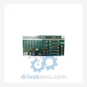
Applied Materials PCB ASSY Modules: 0100-01577
Applied Materials 0100-01577 is listed for Controller Cards RFQ review. Confirm quantity, condition and destination before quotation.
RFQ-ready industrial model
Model: 0100-20077 810-800256-017 0190-34513
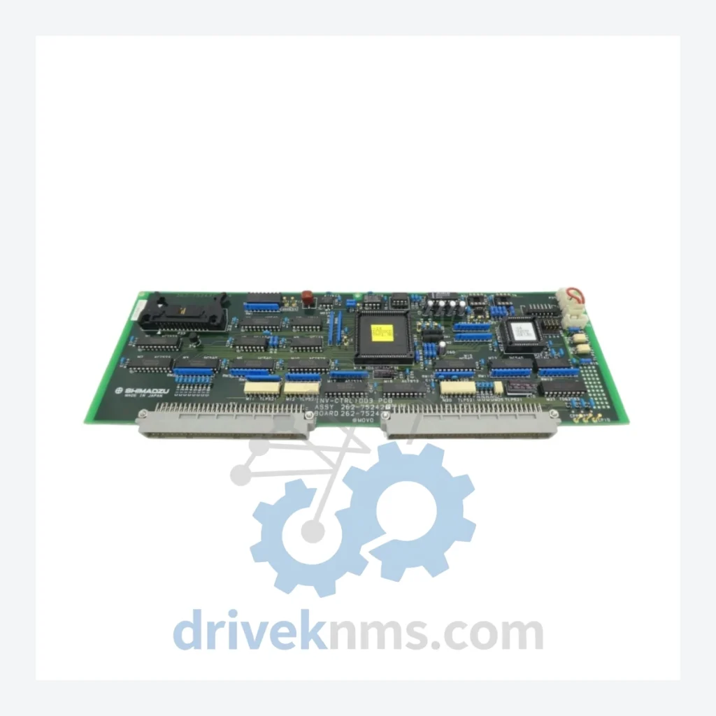
Product Overview
Commercial availability is handled through direct RFQ, model verification and export-oriented follow-up rather than public cart checkout.
Datasheet Preview
Use attached product manuals when available. If the manual is not public yet, request the full file directly through RFQ.
Commercial Path
Product pages on DRIVEKNMS are designed to verify model, brand and series first, then move the buyer into one clean quotation path.
Technical Dossier
RFQ support for obsolete parts: Send the model number, required quantity and destination so DriveKNMS can confirm sourcing options before quotation.
Note: Electrical parameters specific to this board are not published here to prevent misapplication. Contact our technical team for compatibility verification against your system serial number and BOM revision.
Applied Materials process equipment — particularly older CVD, PVD, and etch platforms — was engineered for decade-long service lives in high-throughput fab environments. The control and power distribution PCB assemblies within these systems are deeply integrated: firmware, calibration offsets, and interlock logic are often tied to specific board revisions. When OEM support ends, there is no generic substitute. A board from a different revision can introduce process drift, trigger safety interlocks, or fail qualification entirely.
DriveKNMS specializes in locating, verifying, and supplying exactly this category of hardware for facilities that have made the deliberate choice to extend the productive life of their existing capital assets rather than absorb the disruption of premature platform retirement.
1. Critical Spare Identification Audit
Map every PCB assembly, power supply module, and motion control card in your equipment against current market availability. Boards like the 0100-20077 that carry multiple cross-reference numbers (indicating multiple BOM revisions over the tool's life) are typically the highest-risk items — they were revised precisely because they were failure-prone, and each revision reduces interchangeability with earlier system configurations.
4. Firmware and Configuration Documentation
Before a board fails, document the firmware version, any calibration parameters stored on the board, and the system configuration it supports. For boards that carry onboard non-volatile memory, this documentation is the difference between a straightforward swap and a multi-day re-commissioning exercise.
5. Supplier Qualification for Obsolete Parts
The secondary market for discontinued industrial electronics contains a wide range of quality. Establish a qualified supplier list specifically for obsolete hardware, with documented inspection and testing requirements. DriveKNMS operates a structured incoming inspection process for all legacy parts — detailed in the section below.
Every Applied Materials PCB assembly processed through DriveKNMS undergoes a structured 5-step inspection protocol before it is offered for sale or shipment:
Step 1 – Visual and Physical Inspection
Full board examination under magnification for mechanical damage, solder joint integrity, component seating, and PCB trace condition. Boards with evidence of thermal events, physical impact, or unauthorized repair are rejected at this stage.
Step 2 – Electrolytic Capacitor Assessment
Electrolytic capacitors are the primary age-related failure mode in legacy PCB assemblies. Each capacitor is checked for physical signs of degradation (bulging, electrolyte leakage, vent deformation). Where ESR measurement is feasible, values are compared against component datasheets. Boards with suspect capacitors are either recapped or rejected — they are not offered as-is.
Step 3 – Firmware and Revision Verification
Where accessible, onboard firmware version and board revision markings are documented and cross-referenced against known system compatibility data. This information is provided to the buyer to support pre-installation verification.
Step 4 – Connector and Pin Integrity Check
All edge connectors, header pins, and board-to-board connectors are inspected for corrosion, pin deformation, and contact plating condition. Oxidized contacts are cleaned using appropriate methods; boards with structurally compromised connectors are rejected.
Step 5 – Functional Verification (Where Applicable)
For boards where test fixture support is available, functional power-on testing is performed. Results are documented. Where functional testing is not feasible, this is disclosed explicitly — buyers receive full transparency on the verification scope applied to their specific unit.
Q: How do I know the unit is genuine and not a counterfeit?
A: All units are inspected for OEM markings, date codes, and construction consistency with known-genuine examples. We do not source from unverified brokers. Provenance documentation (where available from the supply chain) is provided upon request.
Q: Can you verify compatibility with my specific tool configuration before I order?
A: Yes. Provide your tool serial number and system BOM revision and our technical team will cross-reference against known compatibility data before confirming the order.
Continue The Model Path
Move from this exact model into the matching system hub, brand archive, model-family archive or lifecycle sourcing route before sending a final RFQ list.
Related Paths
Applied Materials 0100-01577 is listed for Controller Cards RFQ review. Confirm quantity, condition and destination before quotation.
Applied Materials 0200-06355 1220-01011 0242-02385 is listed for Controller Cards RFQ review. Confirm quantity, condition and destination before quotation.
Applied Materials 0040-49884 E7627/Z 0150-00947 is listed for Controller Cards RFQ review. Confirm quantity, condition and destination before quotation.