
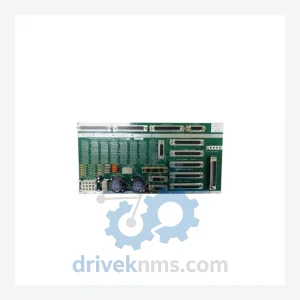
Applied Materials PCB ASSY Modules: 0100-01577
Applied Materials 0100-01577 is listed for Controller Cards RFQ review. Confirm quantity, condition and destination before quotation.
RFQ-ready industrial model
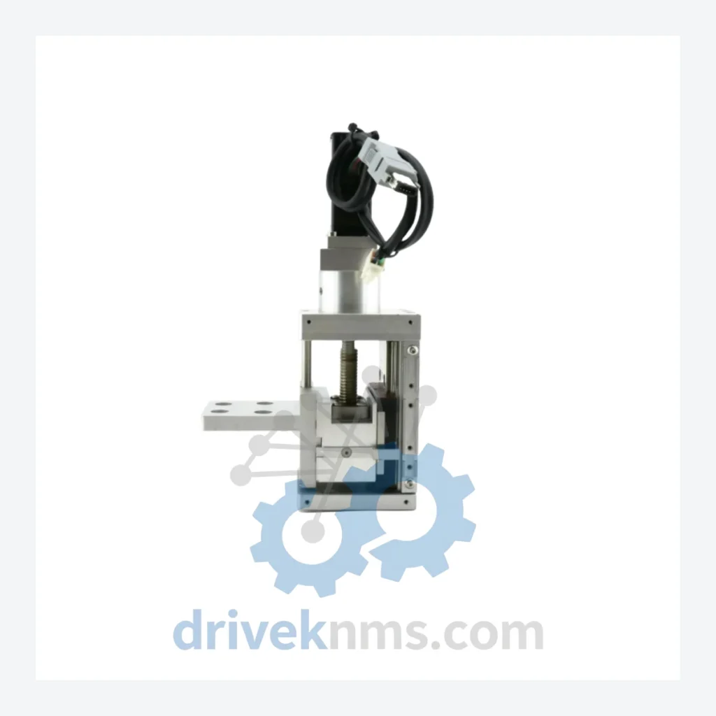
Model: 0190-25081 0200-10265 23HS24 15-01 23S21-0560-8A5L7-55(30)
Product Overview
Commercial availability is handled through direct RFQ, model verification and export-oriented follow-up rather than public cart checkout.
Datasheet Preview
Use attached product manuals when available. If the manual is not public yet, request the full file directly through RFQ.
Commercial Path
Product pages on DRIVEKNMS are designed to verify model, brand and series first, then move the buyer into one clean quotation path.
Technical Dossier
Applied Materials has standardized on NEMA 23 hybrid stepper motor actuator assemblies since the early 1990s across its Centura, Endura, and Producer platform families. The 23HS24 mechanical envelope (57 mm × 57 mm flange, 60 mm stack length) was adopted as a platform-wide standard to reduce spare parts proliferation. Early-generation assemblies used unipolar winding configurations with external driver boards (e.g., Applied Materials driver card 0100-09187). Subsequent revisions transitioned to bipolar series/parallel winding, compatible with microstepping drives operating at 24–48 VDC bus voltage and 1.0–3.0 A/phase current range. The lead-screw pitch variants (0.5 mm, 1.0 mm, 2.0 mm per revolution) were differentiated by the suffix codes embedded in the internal part number string (e.g., 8A5L7-55(30) denotes stroke length and pitch class). Compatibility between generations requires verification of connector pinout (typically Molex Mini-Fit Jr. or AMP CPC series), encoder feedback type (open-loop vs. closed-loop with incremental encoder), and mechanical mounting interface (front-flange vs. rear-flange). Systems transitioning from Centura 200 mm to Centura 300 mm platforms required actuator stroke extension, resulting in parallel part number families that share the 23HS24 motor core but differ in lead-screw assembly length.
The following SKUs represent verified Applied Materials part numbers within or directly associated with the 23HS24 linear actuator assembly family. Classification follows functional role within the equipment subsystem.
Linear Actuator Assemblies (Complete Units)
Motor Sub-Components (23HS24 Motor Core)
Lead-Screw & Mechanical Sub-Assemblies
Driver & Control Interface Cards
Each 23HS24 linear actuator assembly processed by DriveKNMS undergoes a structured inspection and functional test protocol prior to shipment. Motor electrical testing includes: phase resistance measurement (±5% of nameplate value), phase inductance measurement, insulation resistance test at 500 VDC (minimum 100 MΩ), and back-EMF waveform verification using a calibrated oscilloscope at 300 RPM. Mechanical testing includes: lead-screw backlash measurement using a dial indicator (acceptance criterion: ≤0.02 mm), axial play measurement, and full-stroke travel verification under no-load and rated-load conditions. For assemblies with integrated encoder feedback, quadrature output signal integrity is verified across the full stroke. All test data is recorded and retained for a minimum of 5 years. Units that fail any acceptance criterion are quarantined, documented, and either repaired to specification or scrapped. Shipment packaging follows JEDEC J-STD-033 guidelines for ESD-sensitive electromechanical assemblies.
Continue The Model Path
Move from this exact model into the matching system hub, brand archive, model-family archive or lifecycle sourcing route before sending a final RFQ list.
Related Paths
Applied Materials 0100-01577 is listed for Controller Cards RFQ review. Confirm quantity, condition and destination before quotation.
Applied Materials 0200-06355 1220-01011 0242-02385 is listed for Controller Cards RFQ review. Confirm quantity, condition and destination before quotation.
Applied Materials 0010-00098 QDP40-QMB250/500 DLP240-24-1/EJ 0090-A3151 is listed for Controller Cards RFQ review. Confirm quantity, condition and destination before quotation.