
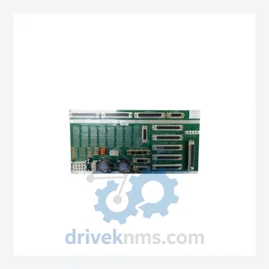
Applied Materials PCB ASSY Modules: 0100-01577
Applied Materials 0100-01577 is listed for Controller Cards RFQ review. Confirm quantity, condition and destination before quotation.
RFQ-ready industrial model
Model: TXZ 0100-01629 GF125C-102895 GF125CXXC N2 280SCCM GF125C-102896 0190-32365 GF125CXXC
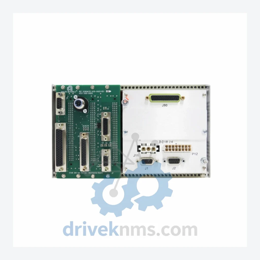
Product Overview
Commercial availability is handled through direct RFQ, model verification and export-oriented follow-up rather than public cart checkout.
Datasheet Preview
Use attached product manuals when available. If the manual is not public yet, request the full file directly through RFQ.
Commercial Path
Product pages on DRIVEKNMS are designed to verify model, brand and series first, then move the buyer into one clean quotation path.
Technical Dossier
DriveKNMS reviews sourcing options for this model through RFQ handling before quotation.
The GF125C-series MFC PCB assembly is not a peripheral accessory — it is the control brain of the gas delivery loop. It governs valve actuation, sensor signal conditioning, and closed-loop flow regulation. In platforms where this module was originally specified, there is no OEM-supported upgrade path that does not require full gas panel re-engineering, new process qualification, and in many cases, updated facility permits.
Every GF125C-series PCB assembly processed through DriveKNMS undergoes a structured 5-step inspection protocol before it is offered for sale. This process is designed specifically for the failure modes common to long-stored or field-removed MFC electronics:
Units are packaged in anti-static bags with desiccant and shipped in rigid foam-lined cartons to prevent transit damage.
Q: Can DriveKNMS source other Applied Materials GF125C-series components?
A: Yes. Contact us with your full part number list and we will advise on availability across the GF125C and GF125CXXC family.
Continue The Model Path
Move from this exact model into the matching system hub, brand archive, model-family archive or lifecycle sourcing route before sending a final RFQ list.
Related Paths
Applied Materials 0100-01577 is listed for Controller Cards RFQ review. Confirm quantity, condition and destination before quotation.
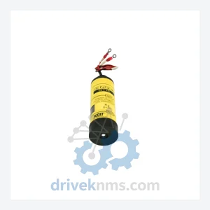
Applied Materials 0200-06355 1220-01011 0242-02385 is listed for Controller Cards RFQ review. Confirm quantity, condition and destination before quotation.
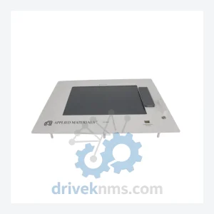
Applied Materials 0040-49884 E7627/Z 0150-00947 is listed for Controller Cards RFQ review. Confirm quantity, condition and destination before quotation.