
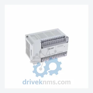
Mitsubishi FX2N-32ER Digital I/O Module – Obsolete MELSEC FX2N Spare Part
Mitsubishi Electric FX2N-32ER is listed for Monitoring Systems RFQ review. Confirm quantity, condition and destination before quotation.
RFQ-ready industrial model
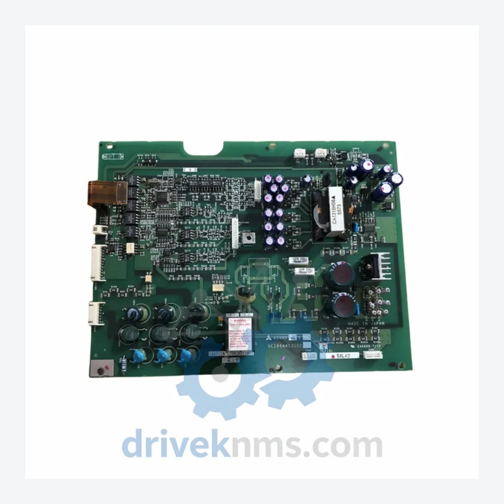
Model: A22MC0.75B BC186A219G52
Product Overview
Commercial availability is handled through direct RFQ, model verification and export-oriented follow-up rather than public cart checkout.
Datasheet Preview
Use attached product manuals when available. If the manual is not public yet, request the full file directly through RFQ.
Commercial Path
Product pages on DRIVEKNMS are designed to verify model, brand and series first, then move the buyer into one clean quotation path.
Technical Dossier
The Mitsubishi Electric FR-A220 series is a line of AC variable-frequency drives (VFDs) engineered for heavy industrial deployment across chemical processing plants, nuclear power auxiliary systems, petroleum refineries, and large-scale HVAC infrastructure. Introduced in the mid-1980s as part of Mitsubishi's second-generation inverter platform, the FR-A220 established the architectural baseline for subsequent FR-A series generations (FR-A240, FR-A500, FR-A700). Units from this series remain installed in long-lifecycle facilities where replacement of the entire drive is cost-prohibitive or operationally disruptive. The A22MC0.75B BC186A219G52 is the power driver board sub-assembly for the 0.75 kW capacity variant, responsible for gate-drive signal conditioning and IGBT/transistor switching control within the main inverter stack.
The FR-A220 series was designed around a discrete transistor switching topology, predating the widespread adoption of IGBT modules in industrial drives. Early variants (0.4 kW–7.5 kW) used bipolar junction transistor (BJT) output stages with analog voltage/frequency (V/f) control. The control board communicated with the power driver board via optocoupler-isolated gate signals — a design that provided noise immunity in high-EMI environments such as arc furnace facilities and motor control centers (MCCs).
As the series matured through the late 1980s and into the 1990s, Mitsubishi introduced revised driver board assemblies (identified by BC186A-prefix board codes) that improved thermal derating characteristics and added short-circuit protection latching. Compatibility between early and late-revision driver boards within the same frame size is not guaranteed without cross-referencing the full board code (e.g., BC186A219G52). Successor platforms — FR-A240, FR-A500, FR-A700, and the current FR-A800 — are not backward-compatible at the board or module level, but serve as functional replacements when full drive substitution is feasible.
The following SKUs represent verified components and sub-assemblies within the Mitsubishi FR-A220 series, organized by functional category. Each entry reflects a discrete, field-replaceable unit (FRU) or board-level assembly.
Power Driver Boards
Control & Main Circuit Boards
Ancillary & Option Modules
FR-A220 power driver boards such as the A22MC0.75B BC186A219G52 undergo a structured inspection and functional verification protocol prior to dispatch. The process addresses the specific failure modes common to this generation of drive hardware:
Continue The Model Path
Move from this exact model into the matching system hub, brand archive, model-family archive or lifecycle sourcing route before sending a final RFQ list.
Related Paths
Mitsubishi Electric FX2N-32ER is listed for Monitoring Systems RFQ review. Confirm quantity, condition and destination before quotation.
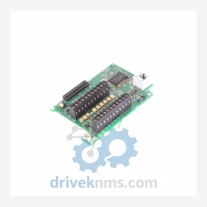
Mitsubishi Electric BC186A512G53 is listed for BC186A Series RFQ review. Confirm quantity, condition and destination before quotation.
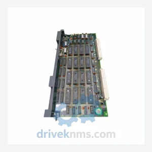
Mitsubishi Electric MW414 MW414B is listed for MW400 Series RFQ review. Confirm quantity, condition and destination before quotation.