
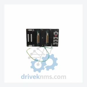
Foxboro RH924YF Mounted Modular Controller – Obsolete I/A Series Spare Part
Foxboro RH924YF is listed for I/A Series RFQ review. Confirm quantity, condition and destination before quotation.
RFQ-ready industrial model
Model: AD916AC FBM202
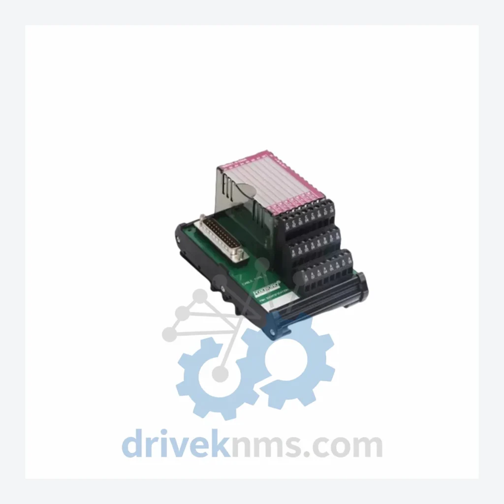
Product Overview
Commercial availability is handled through direct RFQ, model verification and export-oriented follow-up rather than public cart checkout.
Datasheet Preview
Use attached product manuals when available. If the manual is not public yet, request the full file directly through RFQ.
Commercial Path
Product pages on DRIVEKNMS are designed to verify model, brand and series first, then move the buyer into one clean quotation path.
Technical Dossier
The FBM (Field Bus Module) architecture was introduced as part of the Foxboro I/A Series DCS, which launched in the mid-1980s as one of the first fully distributed control systems. The FBM200-series modules represent the analog input tier of this architecture, with the FBM202 specifically addressing thermocouple and mV signal conditioning.
Early FBM202 variants used parallel backplane communication and were designed for the original I/A Series nodebus. As the platform evolved through the 1990s and 2000s, Foxboro introduced revised hardware revisions (denoted by letter suffixes such as AC, AD, AE) that addressed EMI compliance, improved cold junction compensation accuracy, and updated firmware compatibility with later DCS software releases (IACC, FoxCAE, AIM*AT). The AD916AC designation on the FBM202 indicates a specific hardware assembly revision (AD916) with a board-level configuration code (AC), used to track compatibility with specific I/A Series system software versions.
The following SKUs represent verified models within the Foxboro FBM202 thermocouple/mV input module family and closely related FBM200-series analog input modules. Each entry reflects a distinct hardware revision, channel configuration, or signal type variant.
AD916AC FBM202: 16-ch thermocouple/mV input module, hardware rev AC, I/A Series DCS compatible
AD916AA FBM202: 16-ch thermocouple/mV input, early hardware revision AA, original I/A Series nodebus
AD916AB FBM202: 16-ch thermocouple/mV input, revision AB, updated EMI shielding and firmware
AD916AD FBM202: 16-ch thermocouple/mV input, revision AD, enhanced cold junction compensation
AD916AE FBM202: 16-ch thermocouple/mV input, revision AE, latest active production variant
P0916AC FBM202: OEM part number cross-reference for AD916AC, used in some plant documentation
FBM201: 8-ch thermocouple/mV input module, reduced channel count variant for smaller I/O nodes
FBM203: RTD (resistance temperature detector) input module, 8-ch, companion to FBM202 in temperature measurement loops
FBM204: 4–20 mA analog input module, 16-ch, standard process variable input for I/A Series
FBM205: 4–20 mA analog input with HART protocol support, 16-ch
FBM206: Analog output module, 4–20 mA, 8-ch, used for control valve and actuator signals
FBM207: Analog output with HART, 8-ch, paired with FBM205 in HART-enabled loops
FBM211: Discrete input module, 32-ch, 24 VDC, for digital field device status signals
FBM212: Discrete output module, 32-ch, 24 VDC, for solenoid and relay control
FBM220: Pulse input module, for flow meter and turbine meter frequency signals
FBM230: Fieldbus communication module, FOUNDATION Fieldbus H1, for FF device integration
FBM232: PROFIBUS DP communication module, for third-party PROFIBUS field device integration
The FBM202 module presents specific test challenges due to its multi-channel thermocouple signal conditioning circuitry, cold junction compensation (CJC) reference, and nodebus backplane interface. DriveKNMS applies the following test protocol to all FBM202 units prior to dispatch:
Each module undergoes powered functional verification using a calibrated thermocouple simulator across all 16 input channels, covering type J, K, T, E, R, S, and B thermocouple ranges as specified in Foxboro FBM202 product specifications. Cold junction compensation accuracy is verified against a reference temperature standard. Backplane connector integrity is inspected under magnification for pin damage, oxidation, and solder joint fatigue. Firmware revision is read and documented. Modules are burn-in tested under simulated load for a minimum of 24 hours before final inspection and packaging.
Continue The Model Path
Move from this exact model into the matching system hub, brand archive, model-family archive or lifecycle sourcing route before sending a final RFQ list.
Related Paths
Foxboro RH924YF is listed for I/A Series RFQ review. Confirm quantity, condition and destination before quotation.
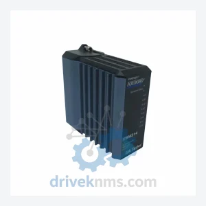
Foxboro FBM204 P0914SY is listed for Series 200 RFQ review. Confirm quantity, condition and destination before quotation.
Foxboro SPEC-200 is listed for Servo Drives RFQ review. Confirm quantity, condition and destination before quotation.