GE Multilin UR Series Modules: UR9GH UR 9GH CPU Module —
GE Multilin UR Series: Comprehensive Module Range and Technical Overview The GE Multilin Universal Relay (UR) Series represents one of…
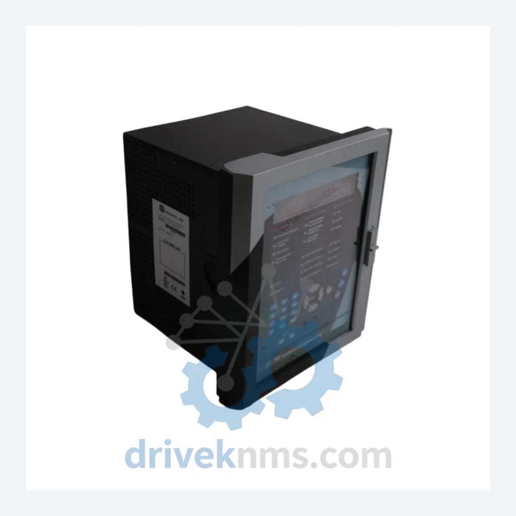
Model: 745-W3-P511-G51-HI-R-E
Product Overview
Commercial availability is handled through direct RFQ, model verification and export-oriented follow-up rather than public cart checkout.
Datasheet Preview
Use attached product manuals when available. If the manual is not public yet, request the full file directly through RFQ.
Commercial Path
Product pages on DRIVEKNMS are designed to verify model, brand and series first, then move the buyer into one clean quotation path.
Technical Dossier
The GE Multilin 745 Transformer Management Relay (TMR) is a purpose-built protection, control, and monitoring platform for power transformers deployed across heavy industrial sectors including petrochemical plants, nuclear power stations, oil refineries, pulp and paper mills, and large-scale utility substations. First introduced in the mid-1990s, the 745 series established a benchmark for multi-function transformer protection by consolidating differential protection, overcurrent, overflux, thermal modeling, and fault recording into a single 19-inch rack-mountable unit. Its installed base spans North America, Europe, and Asia-Pacific, with units still in active service at facilities operating on 20–30 year maintenance cycles. The 745-W3-P511-G51-HI-R-E variant specifically designates a configuration with three-winding capability, standard I/O complement, high-impedance restricted earth fault input, and RS-485 communications — a specification commonly found in refinery main transformer bays and nuclear auxiliary transformer panels.
The 745 platform was developed by GE Multilin (formerly Multilin Inc., acquired by GE in 1994) as a successor to discrete electromechanical and early solid-state transformer protection schemes. The original 745 firmware (v1.x–v2.x) supported two-winding differential protection with basic harmonic restraint. Version 3.x introduced three-winding differential capability, expanded the CT input range, and added DNP 3.0 serial communications alongside the existing Modbus RTU protocol — directly addressing the integration requirements of SCADA systems prevalent in 1990s utility and industrial environments.
Version 4.x and later releases added IEC 61850 GOOSE messaging support (on equipped hardware variants), enhanced oscillography with 64 samples per cycle, and expanded thermal model parameters for ONAN/ONAF/OFAF cooling modes. The hardware platform itself evolved from a single-board architecture to a modular backplane design, allowing field replacement of the power supply, CPU, and I/O boards independently — a critical serviceability feature for installations where relay replacement requires outage coordination.
The 745 series reached end-of-active-production status, with GE Multilin positioning the T60 Transformer Protection System (part of the Universal Relay platform) as the primary modern replacement. However, the T60 uses a fundamentally different hardware and firmware architecture, making direct swap-in replacement non-trivial. Panel cutout dimensions, CT wiring schemes, and SCADA communication configurations all require engineering review during migration. As a result, the 745 remains in active procurement for brownfield maintenance, with demand concentrated on spare relay units, replacement I/O boards, and power supply modules.
The following SKUs represent verified models within the GE Multilin 745 Transformer Management Relay family, organized by functional configuration. Each model number encodes winding count, I/O complement, communication options, and mounting style.
Three-Winding Differential Protection Variants
Two-Winding Differential Protection Variants
Enhanced I/O and Special Function Variants
Replacement and Sub-Assembly Modules
The GE Multilin 745 series is classified as a mature/end-of-life product line. GE Grid Solutions (the successor entity to GE Multilin) has transitioned active support to the T60 platform. This creates a well-defined procurement challenge: facilities operating 745 relays under long-term maintenance agreements or within regulated industries (nuclear, utility) cannot execute unplanned platform migrations and require continued access to like-for-like spare units and sub-assemblies.
DriveKNMS maintains a dedicated inventory program for 745 series components sourced through authorized surplus channels, decommissioned utility equipment, and tested pull units. All units are subject to functional verification prior to dispatch. For obsolete variants where new-old-stock is unavailable, DriveKNMS can facilitate repair-and-return service for CPU boards, power supply modules, and I/O assemblies. Customers operating under IEC 61511 or NERC CIP maintenance frameworks are advised to document the provenance and test records of any replacement relay — DriveKNMS provides full test documentation upon request.
Lead times for common variants such as the 745-W3-P511-G51-HI-R-E and 745-W2-P511-G51-HI-R-E are typically 3–10 business days from confirmed stock. Rare configurations and sub-assembly modules are quoted on a case-by-case basis with a standard 5-business-day sourcing assessment.
The 745 relay's internal architecture presents specific test requirements that differ from standard PLC I/O modules. Key verification procedures applied by DriveKNMS to all 745 series units include:
For sourcing inquiries, technical specifications, or repair assessments on GE Multilin 745 Series relays:
© 2026 DriveKNMS. All trademarks belong to their respective owners. Specifications are for reference only and subject to change without notice. Verify all parameters against official documentation before installation.
Related Paths
GE Multilin UR Series: Comprehensive Module Range and Technical Overview The GE Multilin Universal Relay (UR) Series represents one of…

GE Multilin UR Series: Comprehensive Module Range and Technical Overview The GE Multilin Universal Relay (UR) platform is a modular,…
GE Multilin UR Series: Comprehensive Module Range and Technical Overview The GE Multilin UR (Universal Relay) platform is one of…