
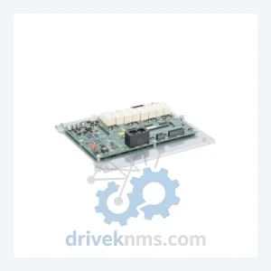
KUKA 00-161-116 Safety Interface Board – KRC Series
Kuka 00-161-116 is listed for KRC Series RFQ review. Confirm quantity, condition and destination before quotation.
RFQ-ready industrial model
Model: 00-138-379
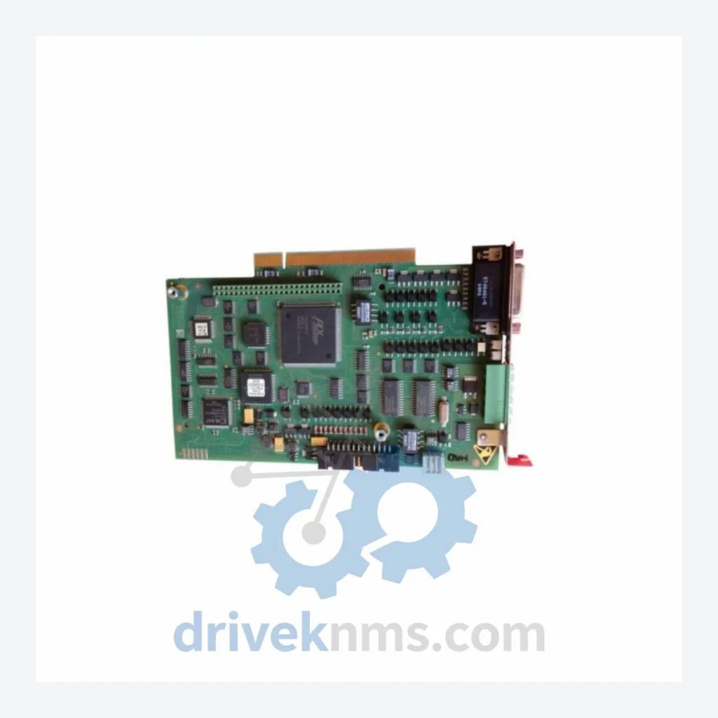
Product Overview
Commercial availability is handled through direct RFQ, model verification and export-oriented follow-up rather than public cart checkout.
Datasheet Preview
Use attached product manuals when available. If the manual is not public yet, request the full file directly through RFQ.
Commercial Path
Product pages on DRIVEKNMS are designed to verify model, brand and series first, then move the buyer into one clean quotation path.
Technical Dossier
The KUKA KRC Safety Board series occupies a critical position in global heavy industrial automation infrastructure. Deployed across chemical processing plants, nuclear facilities, petroleum refineries, and large-scale automotive manufacturing lines, these safety-rated boards form the backbone of KUKA robot controller safety circuits. The KRC (KUKA Robot Controller) platform — spanning KRC1, KRC2, KRC4, and KRC5 generations — relies on dedicated safety boards to enforce EN ISO 10218-1 and IEC 62061 compliance. The 00-138-379 safety board is a representative component of this ecosystem, providing hardware-level safety monitoring for emergency stop circuits, enabling category 3 / PLd safety architecture within the robot controller cabinet.
KUKA's safety board architecture has evolved across four distinct controller generations, each introducing tighter integration between safety logic and motion control:
KRC1 (1996–2003): Early safety boards used discrete relay-based logic with limited diagnostic feedback. Safety monitoring was hardware-only, with no fieldbus integration. Boards from this era are now fully obsolete and require specialist sourcing.
KRC2 (2000–2012): Introduced the ESC (Electronic Safety Circuit) architecture. Safety boards in this generation began integrating dual-channel monitoring and CAN-bus diagnostics. The KRC2 platform remains widely installed in automotive body shops and is the most common source of safety board replacement demand.
KRC4 (2010–present): Transitioned to the SafeOperation and SafeRangeMonitoring software stack, with safety boards now functioning as certified SIL2/PLd hardware nodes. The safety board communicates via EtherCAT with the KPC (controller PC) and KSP (servo power module). Firmware versioning became critical — board swaps require matching firmware to the controller version.
KRC5 (2020–present): Current generation. Safety architecture is further integrated into the controller's main backplane. Legacy KRC2/KRC4 safety boards are not forward-compatible with KRC5 systems.
Compatibility note: Safety boards are generation-locked. A KRC2 safety board cannot be substituted into a KRC4 system without full controller recertification. Always verify the controller generation and ESC version before ordering.
The following SKUs represent verified, commonly sourced components within the KUKA KRC safety board and associated safety circuit ecosystem. Each entry reflects a distinct functional role within the controller architecture.
00-138-379: KRC2/KRC4 safety board; dual-channel ESC monitoring, E-stop circuit control
00-116-342: KRC2 safety interface board; operator panel safety relay integration
00-130-468: KRC2 ESC safety board; category 3 PLd, CAN-bus diagnostic output
00-132-876: KRC4 safety board assembly; EtherCAT node, SIL2 certified dual-channel
00-140-552: KRC4 safety I/O expansion board; 16 DI safety inputs, 8 DO safety outputs
00-141-193: KRC4 customer safety interface board; external safety device integration
00-143-765: KRC4 SafeOperation board; axis-specific safe speed and position monitoring
00-118-924: KRC2 power supply board for safety circuit; 24VDC regulated output
00-127-334: KRC2 main safety relay board; contactor control for drive enable
00-134-021: KRC4 KSB (KUKA System Bus) safety communication board
00-136-887: KRC2 teach pendant safety board; enabling switch circuit monitoring
00-139-450: KRC4 external axis safety interface; 3rd-party servo drive safety integration
00-142-310: KRC4 safety fieldbus adapter; PROFIsafe over PROFINET integration
00-144-098: KRC4 door interlock safety board; cell access monitoring, category 4 PLe
00-146-227: KRC4 advanced safety board; SafeRangeMonitoring with 16-zone configuration
00-148-563: KRC5 safety interface module; backward-compatible safety I/O for KRC5 neo
The KRC1 and KRC2 safety board lines reached end-of-production between 2008 and 2014. KUKA's official spare parts support for KRC2 safety boards entered restricted availability after 2020. For facilities operating legacy KRC2 robot fleets — common in automotive stamping, spot welding, and foundry applications — sourcing replacement safety boards through the standard distribution channel is no longer reliable.
DriveKNMS maintains a dedicated inventory of KRC1 and KRC2 safety boards sourced from decommissioned robot cells, verified OEM overstock, and certified refurbishment programs. Each unit undergoes functional restoration before dispatch. For KRC4 components approaching end-of-life, DriveKNMS offers forward-stocking agreements to ensure continuity for planned maintenance cycles.
Visual Inspection: PCB examined under magnification for capacitor bulge, relay contact wear, trace corrosion, and connector pin deformation. Boards with any physical anomaly are rejected at intake.
Power-On Functional Test: Each board is energized in a matched KRC controller test bench. Safety circuit continuity is verified across all E-stop, enabling switch, and door interlock channels.
Dual-Channel Integrity Check: Both monitoring channels are independently tested for response time and cross-fault detection. Boards must demonstrate correct fault response within the IEC 62061 specified reaction time.
Firmware Version Logging: The installed firmware version is recorded and documented with each unit. Customers are advised of the firmware version prior to shipment to confirm compatibility with their controller revision.
Burn-In Cycle: Boards are operated under load for a minimum of 4 hours to screen for early-life component failures before dispatch.
Continue The Model Path
Move from this exact model into the matching system hub, brand archive, model-family archive or lifecycle sourcing route before sending a final RFQ list.
Related Paths
Kuka 00-161-116 is listed for KRC Series RFQ review. Confirm quantity, condition and destination before quotation.
Kuka 00-127-754 is listed for Controller Cards RFQ review. Confirm quantity, condition and destination before quotation.
Kuka KRC4 00-183-926A1-X3 is listed for KRC4 RFQ review. Confirm quantity, condition and destination before quotation.