
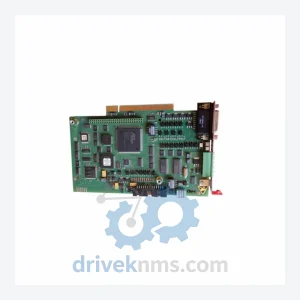
KUKA KRC Safety Board Modules: 00-138-379
Kuka 00-138-379 is listed for Controller Cards RFQ review. Confirm quantity, condition and destination before quotation.
RFQ-ready industrial model
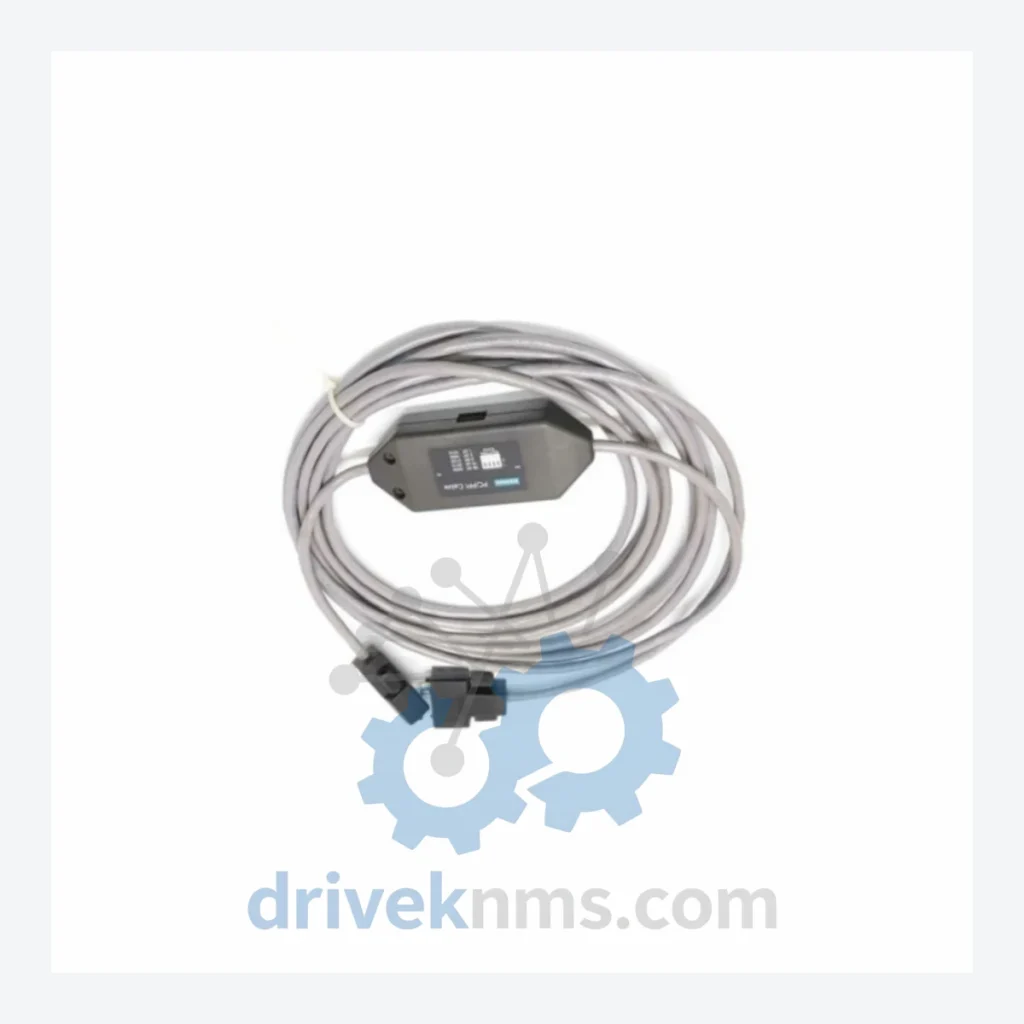
Model: 00-176-028 C4 00-277-094 00-170-196
Product Overview
Commercial availability is handled through direct RFQ, model verification and export-oriented follow-up rather than public cart checkout.
Datasheet Preview
Use attached product manuals when available. If the manual is not public yet, request the full file directly through RFQ.
Commercial Path
Product pages on DRIVEKNMS are designed to verify model, brand and series first, then move the buyer into one clean quotation path.
Technical Dossier
The KR C4 architecture was introduced in 2009 as a successor to the KR C2 (1996) and KR C2 ed05 (2004) platforms. Key architectural transitions:
KR C2 era (1996–2008): Proprietary VxWorks RTOS, DSE-IBS backplane bus, KCP2 pendant with serial RS-485 link. No Ethernet-based fieldbus native support. SmartPAD connectivity used a dedicated 25-pin D-sub harness.
KR C2 ed05 (2004–2010): Introduced Windows XP Embedded host OS alongside VxWorks real-time partition. KCP2 pendant retained. Partial EtherCAT support via optional CI3 card.
KR C4 (2009–present): Full PC-based architecture. Intel Core i5/i7 IPC. KSS 8.x operating system. SmartPAD (KCP4) connected via X19 Ethernet-over-USB hybrid interface. Supports KUKA.PLC mxAutomation, KUKA.SafeOperation, KUKA.ServoGun. Native EtherCAT, PROFINET, DeviceNet, EtherNet/IP fieldbus support via plug-in technology (KEB). The X19 interface assembly — comprising parts 00-176-028, 00-277-094, and 00-170-196 — provides the physical and electrical bridge between the KR C4 cabinet backplane and the SmartPAD pendant cable.
KR C4 compact (2013–present): Reduced footprint variant for small robots (KR AGILUS). Same X19 SmartPAD interface standard.
KR C5 (2020–present): Next-generation successor. Smaller form factor, integrated safety PLC, updated pendant interface. KR C4 parts remain in active demand for installed base maintenance.
Compatibility note: KR C4 SmartPAD interface components are not backward-compatible with KR C2 cabinets. KR C5 uses a revised X19 connector standard; cross-generation substitution requires engineering validation.
The following SKUs represent verified components within the KUKA KR C4 ecosystem. Classified by functional category:
SmartPAD Interface & Pendant Components
00-176-028: KR C4 SmartPAD X19 interface board, cabinet-side connector assembly
00-277-094: KR C4 SmartPAD X19 cable harness, pendant-to-cabinet link
00-170-196: KR C4 SmartPAD X19 interface bracket and strain relief assembly
00-168-334: SmartPAD KCP4 teach pendant, complete unit with enabling device
00-220-947: SmartPAD cable 10m extension, X19 compatible
00-220-948: SmartPAD cable 20m extension, X19 compatible
Controller Power Supply Modules
00-130-468: KR C4 primary power supply unit, 24VDC cabinet rail
00-116-474: KR C4 servo power supply, DC bus feed module
00-134-922: KR C4 UPS module, uninterruptible power buffer for IPC
Safety & Drive Interface Modules
00-160-185: KR C4 safety interface board (SIB), dual-channel safety monitoring
00-160-186: KR C4 safety interface board extended (SIB-Ext), additional safe I/O
00-109-403: KR C4 KPP (KUKA Power Pack), servo drive power module
00-109-404: KR C4 KSP (KUKA Servo Pack), axis drive amplifier module
Communication & Fieldbus Modules
00-174-889: KR C4 PROFINET IO controller interface card
00-174-890: KR C4 EtherNet/IP adapter module
00-174-891: KR C4 DeviceNet master interface card
00-174-892: KR C4 EtherCAT master interface module
IPC & Backplane Components
00-168-351: KR C4 industrial PC (IPC) main board, Intel Core i5
00-168-352: KR C4 IPC main board, Intel Core i7 variant
00-130-469: KR C4 backplane bus board, internal cabinet interconnect
KR C4 SmartPAD interface assemblies involve multi-layer PCB construction with high-density connector arrays and mixed-signal circuitry. DriveKNMS applies the following test protocol to all KR C4 interface components prior to dispatch:
Visual & Mechanical Inspection: Connector pin integrity check (X19 50-pin array), PCB trace inspection under 10x magnification, housing crack and latch integrity verification.
Electrical Continuity Test: Full pin-to-pin continuity mapping against KUKA wiring diagram 00-176-028 Rev. C reference. Isolation resistance test at 500VDC between signal and shield planes.
Functional Bus Communication Test: Interface board installed in KR C4 test cabinet running KSS 8.6. SmartPAD enumeration verified. X19 USB-over-Ethernet handshake confirmed. Pendant display, enabling device, and emergency stop channel validated.
Burn-In Cycle: 4-hour thermal soak at 45°C ambient with active SmartPAD communication loop. Post-soak re-test of all electrical parameters.
All units ship with a DriveKNMS test certificate referencing serial number, test date, and pass/fail criteria results.
Continue The Model Path
Move from this exact model into the matching system hub, brand archive, model-family archive or lifecycle sourcing route before sending a final RFQ list.
Related Paths
Kuka 00-138-379 is listed for Controller Cards RFQ review. Confirm quantity, condition and destination before quotation.
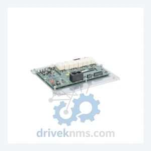
Kuka 00-161-116 is listed for KRC Series RFQ review. Confirm quantity, condition and destination before quotation.
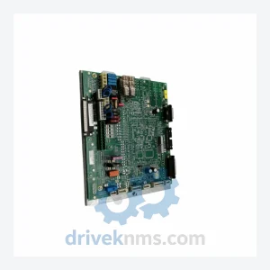
Kuka 00-127-754 is listed for Controller Cards RFQ review. Confirm quantity, condition and destination before quotation.