
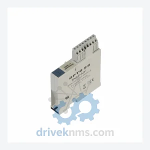
OPTO 22 SNAP-AIV Analog Input Module – Obsolete SNAP I/O Spare Part
Opto 22 SNAP-AIV is listed for Monitoring Systems RFQ review. Confirm quantity, condition and destination before quotation.
RFQ-ready industrial model
Model: SNAP-PS5
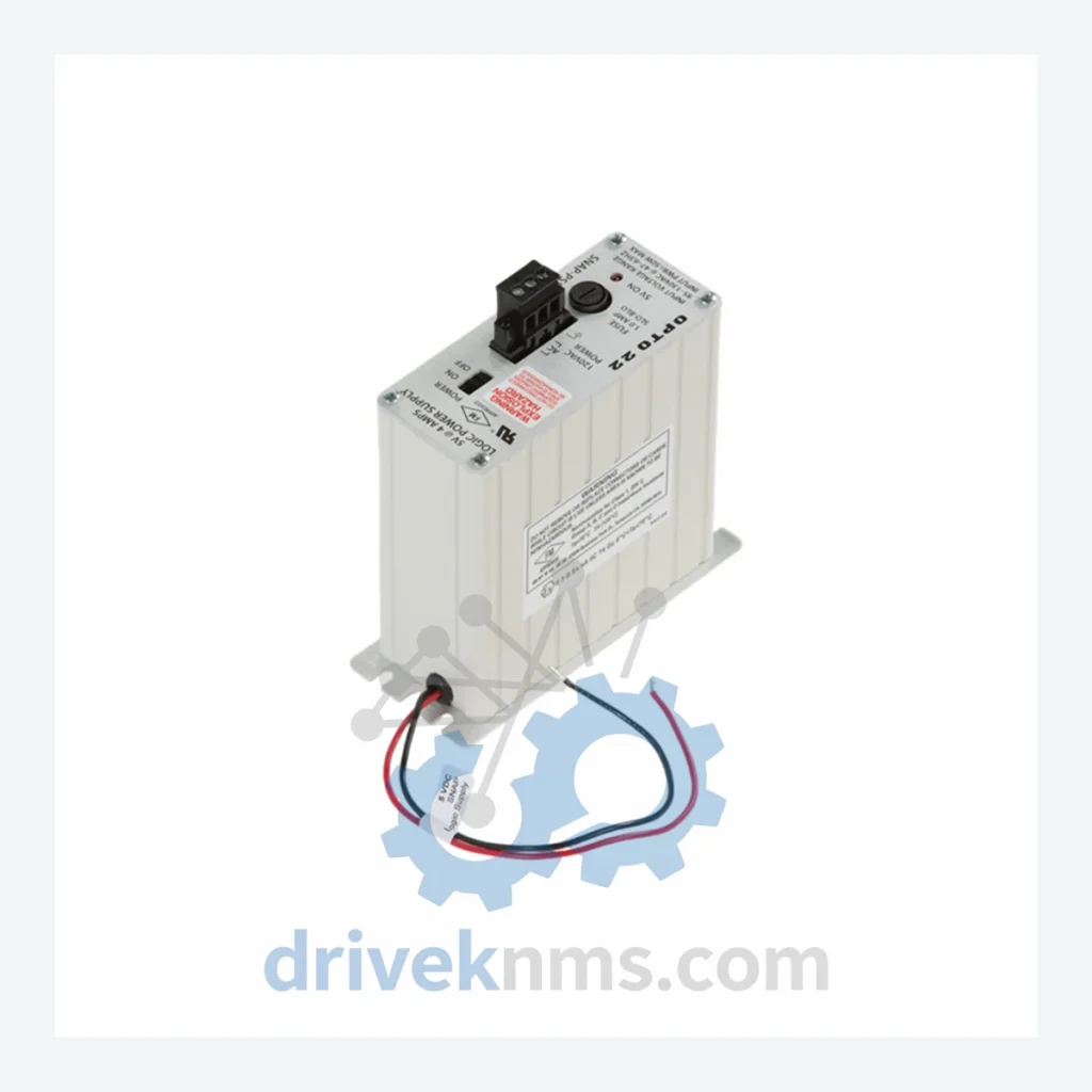
Product Overview
Commercial availability is handled through direct RFQ, model verification and export-oriented follow-up rather than public cart checkout.
Datasheet Preview
Use attached product manuals when available. If the manual is not public yet, request the full file directly through RFQ.
Commercial Path
Product pages on DRIVEKNMS are designed to verify model, brand and series first, then move the buyer into one clean quotation path.
Technical Dossier
The OPTO 22 SNAP (Simple Networking and Automation Platform) series represents one of the most widely deployed modular I/O architectures in global heavy industry. Installed across petrochemical refineries, nuclear power generation facilities, offshore platforms, and large-scale chemical processing plants, SNAP hardware is recognized for its deterministic signal conditioning, open-protocol communication, and field-replaceable module design. The platform's distributed I/O topology allows control engineers to position signal acquisition points at the process level, reducing wiring runs and improving noise immunity in high-EMI environments. SNAP systems are found in both standalone PAC (Programmable Automation Controller) configurations and as remote I/O nodes integrated into third-party DCS and SCADA architectures via OPC-UA, Modbus TCP, and PROFINET adapters.
The SNAP platform was introduced by OPTO 22 in the mid-1990s as a successor to its earlier G4 and Pamux I/O families. The original SNAP architecture used a parallel backplane bus with dedicated mounting racks (SNAP-B series) and relied on analog and discrete signal modules communicating through a local processor brain. Early brain modules such as the SNAP-LCE and SNAP-LCSX provided serial and Ethernet connectivity respectively, establishing the foundation for network-distributed I/O.
The second architectural generation introduced the SNAP PAC family — SNAP-PAC-R1, SNAP-PAC-R2, SNAP-PAC-S1, SNAP-PAC-S2 — which unified the controller and I/O brain into a single programmable unit running the groov EPIC firmware stack. This generation added IEC 61131-3 programming compliance, RESTful API access, and MQTT/Sparkplug B support, enabling direct integration with cloud-based SCADA and IIoT platforms without middleware.
Compatibility considerations are significant across generations: original SNAP mounting racks (SNAP-B series) are physically and electrically compatible with both legacy brain modules and current PAC brains, preserving installed-base investments. However, SNAP-LCE and SNAP-LCSX brains are no longer manufactured and require lifecycle sourcing from specialist distributors. Signal modules (analog, discrete, serial) maintain backward compatibility across all rack generations, making module-level replacement straightforward even in mixed-generation installations.
The following SKUs represent the core SNAP series module range, organized by functional category. Each entry reflects a verified, commercially documented part number within the OPTO 22 SNAP product family.
Power Supplies
Mounting Racks
Brain / Controller Modules
Analog Input Modules
Analog Output Modules
Discrete I/O Modules
SNAP modules present specific test challenges due to their backplane bus architecture and optically isolated signal paths. DriveKNMS applies a structured verification protocol to all SNAP inventory:
Continue The Model Path
Move from this exact model into the matching system hub, brand archive, model-family archive or lifecycle sourcing route before sending a final RFQ list.
Related Paths
Opto 22 SNAP-AIV is listed for Monitoring Systems RFQ review. Confirm quantity, condition and destination before quotation.
Opto 22 001818K AC24 AT is listed for AC24 Series RFQ review. Confirm quantity, condition and destination before quotation.
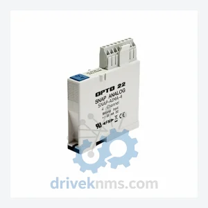
Opto 22 SNAP-AIMA-I is listed for Monitoring Systems RFQ review. Confirm quantity, condition and destination before quotation.