
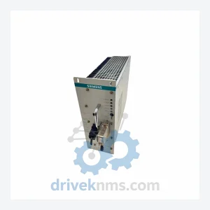
Siemens S31043 Rectifier Modules S31043-K1166-X
Siemens S31043-K1166-X is listed for Controller Cards RFQ review. Confirm quantity, condition and destination before quotation.
RFQ-ready industrial model
Model: A1A10000350.00M
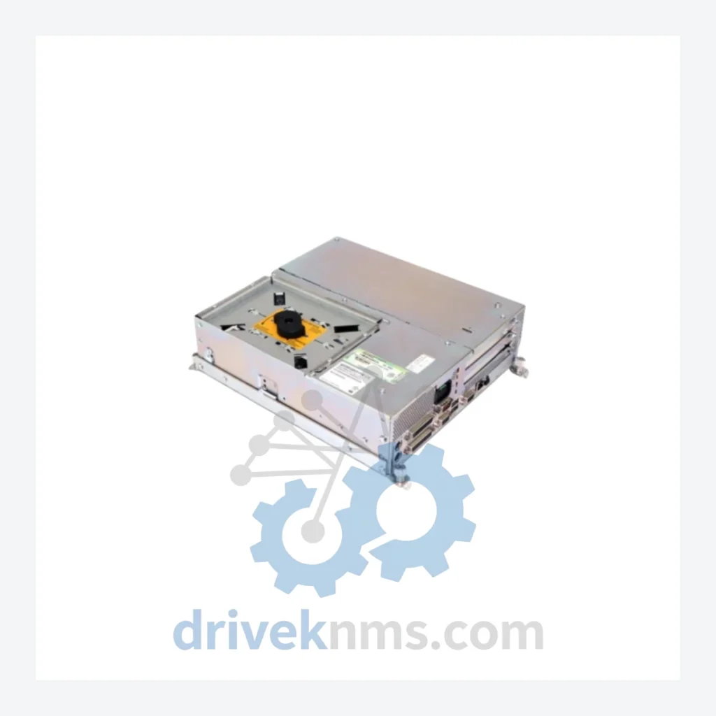
Product Overview
Commercial availability is handled through direct RFQ, model verification and export-oriented follow-up rather than public cart checkout.
Datasheet Preview
Use attached product manuals when available. If the manual is not public yet, request the full file directly through RFQ.
Commercial Path
Product pages on DRIVEKNMS are designed to verify model, brand and series first, then move the buyer into one clean quotation path.
Technical Dossier
The Siemens Robicon series represents one of the most widely deployed medium-voltage variable frequency drive (MV-VFD) platforms in global heavy industry. Installed across petrochemical refineries, nuclear power auxiliary systems, offshore platforms, and large-scale chemical processing facilities, Robicon drives are recognized for their multi-cell cascaded H-bridge topology, which delivers near-sinusoidal output waveforms without the need for output filters. The A1A10000350.00M is a modulator board within this architecture, responsible for generating the PWM gate signals that coordinate switching across the power cell array. Its failure directly impacts drive output quality and motor control precision, making it a critical spare in any Robicon-equipped facility.
The Robicon product line originated with Robicon Corporation, founded in Pittsburgh, Pennsylvania, and was acquired by Siemens in 2002, subsequently integrated into the Siemens SINAMICS and Perfect Harmony product families. The core cascaded H-bridge architecture has remained consistent across generations, but control electronics have evolved significantly:
Generation 1 (Pre-2002, Robicon Corp era): Analog-dominant control boards, discrete gate driver circuits, limited diagnostics. Many boards in this generation are now fully obsolete with no OEM support.
Generation 2 (2002–2010, Siemens integration phase): Introduction of DSP-based modulator boards (including the A1A10000350.00M family), fiber-optic gate signal transmission, and structured fault code architecture. Compatibility between Gen 1 and Gen 2 control boards requires careful cross-referencing of backplane connector pinouts.
Generation 3 (2010–present, Perfect Harmony GH180/GH150): Fully digital control, EtherNet/IP and PROFIBUS integration, enhanced thermal management. The GH180 is the current production successor. However, a large installed base of Gen 2 Robicon drives remains in service globally, creating sustained demand for boards such as the A1A10000350.00M.
Compatibility note: A1A-prefix boards are generally not interchangeable with A1B-prefix or GH-series boards without engineering review of firmware and backplane interface versions.
The following SKUs represent verified components within the Siemens Robicon MV-VFD ecosystem, organized by functional category:
Modulator & Control Boards
A1A10000350.00M: PWM modulator board; generates gate drive signals for cascaded H-bridge power cells.
A1A10000351.00M: Modulator board variant; alternate firmware revision for specific cell count configurations.
A1A10000352.00M: Modulator board; used in higher-voltage (6.6kV–11kV) Robicon drive configurations.
A1A10000100.00M: Main control board (MCB); primary CPU for drive logic, speed reference processing, and fault management.
A1A10000101.00M: Main control board variant; extended I/O version for multi-motor or tandem drive setups.
A1A10000200.00M: Interface board; manages communication between MCB and power cell gate driver boards.
Gate Driver & Power Cell Boards
A1A10000400.00M: Gate driver board; interfaces modulator signals to IGBT switching devices within each H-bridge cell.
A1A10000401.00M: Gate driver board; high-current variant for 690V-class power cells.
A1A10000450.00M: Power cell bypass board; enables automatic cell bypass upon cell fault detection to maintain drive operation.
A1A10000500.00M: Fiber-optic receiver board; converts optical gate signals to electrical for IGBT drivers.
I/O & Communication Modules
A1A10000600.00M: Analog I/O board; processes speed reference, current feedback, and torque signals.
A1A10000601.00M: Digital I/O expansion board; adds discrete input/output capacity for external interlocks and status signals.
A1A10000700.00M: PROFIBUS DP communication adapter; enables fieldbus integration with DCS/PLC systems.
A1A10000701.00M: DeviceNet communication adapter; used in North American installations with Allen-Bradley PLC infrastructure.
Power Supply Boards
A1A10000800.00M: Control power supply board; provides regulated 24VDC and ±15VDC rails to control electronics.
A1A10000801.00M: Redundant power supply module; used in high-availability configurations requiring uninterrupted control power.
A1A10000900.00M: Auxiliary power board; supplies isolated power to fiber-optic transmitter circuits and cell monitoring hardware.
For facilities operating Robicon drives beyond their original design life, DriveKNMS also provides lifecycle extension consulting, including spare parts planning, recommended stocking levels by drive rating, and obsolescence risk assessments.
Robicon modulator and control boards present specific test challenges due to their dependence on fiber-optic signal integrity, multi-rail power supply sequencing, and real-time PWM timing accuracy. DriveKNMS applies the following test procedures to all Robicon boards prior to dispatch:
Power-on sequencing test: All supply rails (24VDC, ±15VDC, 5VDC) are verified for correct voltage, ripple, and sequencing order per Siemens service documentation.
Fiber-optic loopback test: Transmitter and receiver circuits on modulator boards are tested for optical power output and signal integrity using calibrated optical power meters.
PWM output verification: Gate signal timing, dead-time intervals, and carrier frequency accuracy are measured against Siemens factory specifications using a digital oscilloscope and logic analyzer.
Thermal stress cycle: Boards are subjected to a controlled thermal cycle (ambient to 55°C and back) to identify latent solder joint failures or component drift.
Functional drive simulation: Where test fixtures are available, boards are installed in a Robicon drive test rig and operated under no-load conditions to verify end-to-end control loop functionality.
All test results are logged and provided with the shipped unit as part of the quality documentation package.
Continue The Model Path
Move from this exact model into the matching system hub, brand archive, model-family archive or lifecycle sourcing route before sending a final RFQ list.
Related Paths
Siemens S31043-K1166-X is listed for Controller Cards RFQ review. Confirm quantity, condition and destination before quotation.
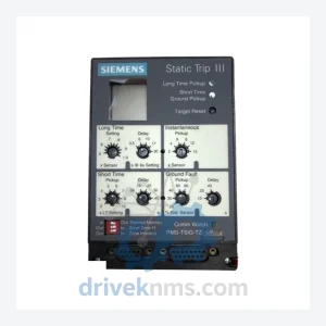
Siemens RMS-TSG-TZ-C is listed for Controller Cards RFQ review. Confirm quantity, condition and destination before quotation.
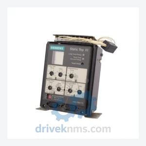
Siemens RMS-TSIG-TZ-C is listed for Controller Cards RFQ review. Confirm quantity, condition and destination before quotation.