Yaskawa YPHT11014-1A Circuit Board – Obsolete Drive Control Spare Part
Yaskawa YPHT11014-1A Circuit Board – Obsolete Drive Control Spare Part When a Yaskawa YPHT11014-1A circuit board fails in a production…
Model: DX200 CPS-520F2 JZNC-YPS21-E MP300¡¢MP350 50999-2922R08
Product Overview
Commercial availability is handled through direct RFQ, model verification and export-oriented follow-up rather than public cart checkout.
Datasheet Preview
Use attached product manuals when available. If the manual is not public yet, request the full file directly through RFQ.
Commercial Path
Product pages on DRIVEKNMS are designed to verify model, brand and series first, then move the buyer into one clean quotation path.
Technical Dossier
The Yaskawa DX200 is a multi-robot controller platform deployed across heavy industrial sectors including automotive body-in-white assembly, chemical processing facilities, nuclear maintenance robotics, and oil refinery automation. Introduced as the successor to the NX100 and XRC controller families, the DX200 supports coordinated control of up to eight robots and 72 axes simultaneously. Its installed base spans facilities in Japan, the United States, Germany, China, and South Korea, making it one of the most widely maintained robot controller architectures in global industrial service inventories.
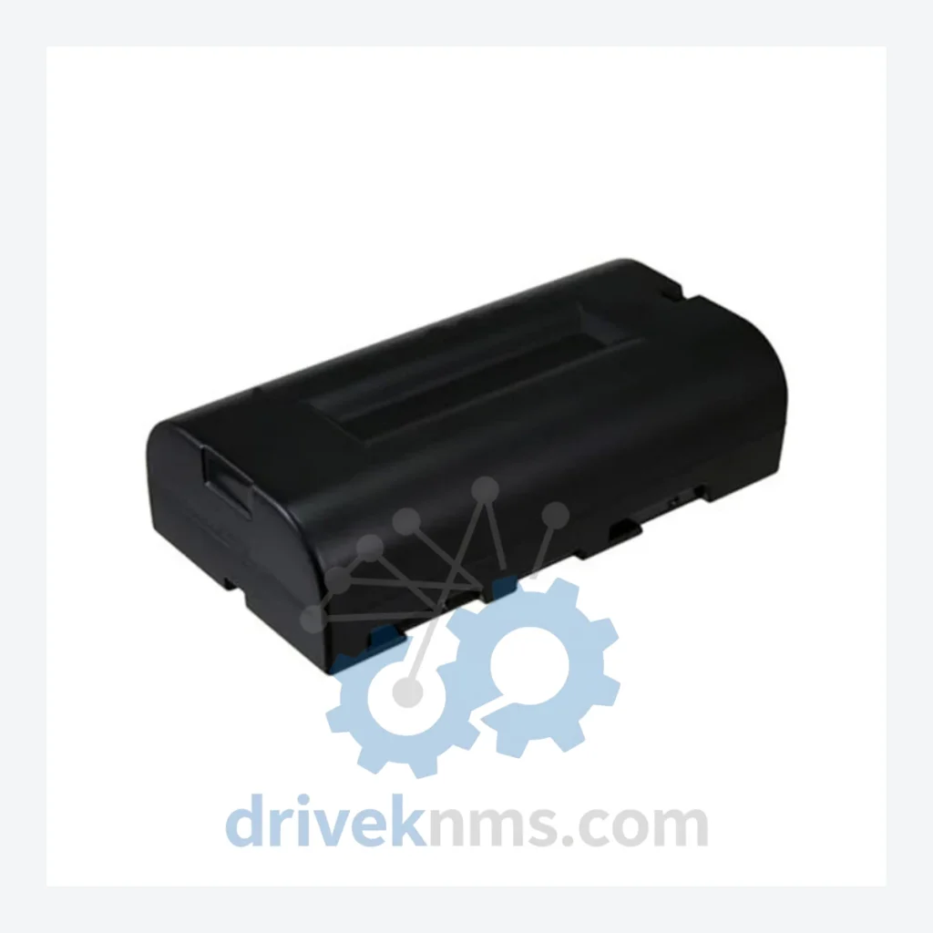
The CPS-520F2 (JZNC-YPS21-E) is the primary power supply unit within the DX200 controller cabinet. It converts AC input to regulated DC rails that power the CPU rack, I/O backplane, and servo amplifier communication buses. The part number 50999-2922R08 identifies the battery assembly integrated within or associated with this power supply unit, responsible for retaining SRAM data, program memory, and real-time clock values during power-off states. Failure of this battery results in loss of job programs, system parameters, and calibration data upon power cycling — a critical failure mode in production environments.
Yaskawa's robot controller architecture has progressed through several generations, each introducing expanded axis capacity, improved network integration, and updated hardware platforms:
XRC (1998–2004): The XRC controller introduced a modular rack architecture with dedicated CPU, I/O, and servo control boards. Memory backup relied on lithium coin cells soldered to individual PCBs, requiring board-level replacement when batteries depleted.
NX100 (2004–2008): The NX100 consolidated controller functions into a more compact chassis. It introduced the JZNC-YPS series power supply family and standardized the battery backup architecture that would carry forward into the DX100 and DX200 generations. Compatibility between NX100 and DX200 power supply modules is limited; cross-generation substitution requires engineering verification.
DX100 (2008–2012): The DX100 served as a transitional platform, sharing backplane connector standards with the DX200 in some configurations. Certain I/O modules (JANCD-YIO series) are interchangeable between DX100 and DX200 racks, though firmware versions must be matched.
DX200 (2012–present): The DX200 introduced a 64-bit processing architecture, EtherNet/IP and DeviceNet native support, and an expanded safety circuit (Functional Safety Unit, FSU). The power supply family was redesigned; the CPS-520F2 / JZNC-YPS21-E is the standard unit for the primary controller cabinet. The DX200 is currently in its mature phase; Yaskawa has introduced the YRC1000 as the next-generation platform, but DX200 installations continue to operate across global facilities with active spare parts demand projected through 2035+.
YRC1000 / YRC1000micro (2016–present): The current-generation controller. Not backward-compatible with DX200 power supply or I/O modules. Facilities migrating from DX200 to YRC1000 must replace the full controller cabinet assembly.
The following SKUs represent verified components within the Yaskawa DX200 controller ecosystem, organized by functional category:
Power Supply Units
JZNC-YPS21-E (CPS-520F2): Primary AC/DC power supply, 520W, DX200 main cabinet
JZNC-YPS22-E: Secondary power supply unit for expanded axis configurations
50999-2922R08: Battery assembly for SRAM and RTC backup within CPS-520F2
CPU & Main Control Boards
JANCD-YCP01-E: Main CPU board, DX200 controller, 64-bit architecture
JANCD-YCP02-E: Dual-CPU board for high-availability and coordinated multi-robot control
JANCD-YSF21-E: Functional Safety Unit (FSU) board, IEC 61508 SIL2 compliant
JANCD-YSF22-E: Expanded FSU module for additional safety I/O channels
I/O Modules
JANCD-YIO21-E: Standard digital I/O module, 32DI / 32DO, DX200 rack-mount
JANCD-YIO22-E: Expanded I/O module, 64DI / 64DO configuration
JANCD-YIO23-E: Analog I/O module, 8AI / 4AO, for process signal integration
JANCD-YEW01-E: EtherNet/IP communication adapter, scanner/adapter mode
Servo & Axis Control
SGDR-AXA01A: Servo amplifier unit, single-axis, DX200 compatible
SGDR-AXA02A: Dual-axis servo amplifier module
JANCD-YSV21-E: Servo control interface board, connects CPU rack to amplifier section
JANCD-YSV22-E: High-speed servo interface for coordinated multi-axis applications
Communication & Network Adapters
JANCD-YEW02-E: DeviceNet master/slave communication module
JANCD-YEW03-E: PROFIBUS-DP adapter, DX200 rack-mount
JANCD-YEW04-E: CC-Link communication module for Mitsubishi network integration
Operator Interface & Pendant
JZRCR-YPP21-1: DX200 programming pendant (teach pendant), color LCD, IP54
JZRCR-YPP21-2: Pendant with expanded function key layout for multi-robot operation
The DX200 platform entered its mature lifecycle phase following the commercial release of the YRC1000 in 2016. Yaskawa's official spare parts support for DX200 components remains active, but lead times for certain PCB assemblies — particularly CPU boards and power supply units — have extended as production volumes shift toward current-generation hardware.
DriveKNMS maintains a dedicated inventory of DX200 spare parts sourced through authorized distribution channels and verified secondary market suppliers. For components classified as end-of-life (EOL) or with extended factory lead times, DriveKNMS provides:
- Verified pull stock from decommissioned DX200 cabinets, inspected and tested prior to sale
- Cross-reference support for identifying functional equivalents within the DX200 family
- Long-term supply agreements for facilities operating large DX200 fleets requiring multi-year maintenance coverage
- Emergency same-day quotation for production-critical failures
The CPS-520F2 / JZNC-YPS21-E and its associated battery 50999-2922R08 are among the highest-demand DX200 components due to the battery's finite service life (typically 3–5 years under standard operating conditions). DriveKNMS stocks both the complete power supply assembly and the battery sub-component to support facilities that perform in-house battery replacement rather than full unit swap.
DX200 controller modules present specific test challenges due to the platform's integrated backplane bus architecture and the interdependency between CPU, I/O, and servo control boards. DriveKNMS applies the following verification procedures to all DX200 components prior to shipment:
Power Supply Units (CPS-520F2 / JZNC-YPS21-E): Full load testing at rated output (520W). DC rail voltage verification: +5V, +12V, +24V, −12V within ±2% tolerance. Inrush current measurement. Battery voltage check (3.0V minimum threshold for 50999-2922R08 cell). Thermal cycling test: 30-minute operation at ambient 40°C.
CPU Boards (JANCD-YCP series): Boot sequence verification using DX200 test rack. SRAM read/write integrity check. Communication bus handshake test with I/O and servo interface boards. Firmware version identification and documentation.
I/O Modules (JANCD-YIO series): Point-by-point digital I/O channel verification using automated test fixture. Analog channel calibration check against reference signal. Backplane connector pin inspection under 10× magnification.
Servo Interface Boards (JANCD-YSV series): Encoder signal simulation test. Axis enable/disable command response verification. Communication latency measurement against DX200 specification.
All tested units are issued a DriveKNMS inspection report documenting test results, firmware version (where applicable), and technician identification. Units that fail any test parameter are quarantined and not offered for sale.
Related Paths
Yaskawa YPHT11014-1A Circuit Board – Obsolete Drive Control Spare Part When a Yaskawa YPHT11014-1A circuit board fails in a production…
Yaskawa YPCT11065-1-3 Circuit Board – Obsolete Varispeed Series Spare Part When a circuit board like the YPCT11065-1-3 fails inside a…
Yaskawa SGMG Series: Comprehensive Module Range and Technical Overview The Yaskawa SGMG series represents one of the most widely deployed…