
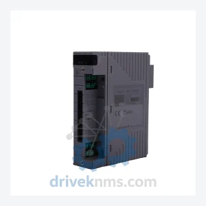
Yokogawa AAI141-S00 Analog Input Module – CENTUM VP S2 Series
Yokogawa AAI141-S00 is listed for CENTUM VP RFQ review. Confirm quantity, condition and destination before quotation.
RFQ-ready industrial model
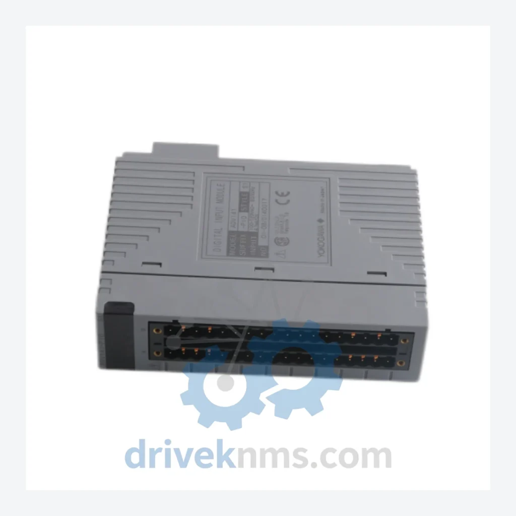
Model: ADV141-P10 S1
Product Overview
Commercial availability is handled through direct RFQ, model verification and export-oriented follow-up rather than public cart checkout.
Datasheet Preview
Use attached product manuals when available. If the manual is not public yet, request the full file directly through RFQ.
Commercial Path
Product pages on DRIVEKNMS are designed to verify model, brand and series first, then move the buyer into one clean quotation path.
Technical Dossier
The YOKOGAWA ADV141 series represents a core family of Digital Input (DI) modules deployed within the CENTUM VP and CENTUM CS 3000 Distributed Control Systems. These modules are installed across the most demanding segments of global heavy industry, including petrochemical complexes, nuclear power generation facilities, offshore oil and gas platforms, and large-scale refinery operations. The ADV141 family interfaces field-level discrete signals — valve position feedback, motor run/stop status, interlock trip signals — into the CENTUM process control backbone via the Vnet/IP or ESB bus architecture. Their role in safety-critical process monitoring makes them among the most frequently maintained and replaced I/O components in long-lifecycle DCS installations worldwide.
The ADV141 lineage traces to the original CENTUM CS (released 1993) and its successor CENTUM CS 3000 (1998), where discrete I/O modules were designed around a card-and-nest architecture using the ESB (Extended Station Bus). Each module occupied a defined slot within an I/O nest (e.g., ANB10D, ANB11D), with the field terminal unit (FTU) providing the physical wiring interface via a dedicated cable harness.
With the introduction of CENTUM VP (2008), YOKOGAWA maintained backward hardware compatibility for the ADV141 form factor while migrating the communication layer to Vnet/IP — a 1 Gbps redundant Ethernet-based control network. This architectural continuity allowed existing ADV141 modules to be retained in brownfield VP migrations, significantly reducing upgrade costs for end users. However, firmware and configuration tools diverged: CS 3000 modules are managed via SystemView, while VP modules require CENTUM VP Engineering Environment (ENG). Cross-generation substitution requires careful revision-level verification.
The following SKUs represent verified, commonly deployed modules within the ADV141 and closely related ADV/ADV1xx DI module family for CENTUM CS 3000 and CENTUM VP systems. Modules are categorized by functional role:
Digital Input (DI) Modules — 32-Channel
Digital Input (DI) Modules — 16-Channel
Digital Output (DO) Modules — Related Family
Analog Input (AI) Modules — Cross-Reference
Communication & Bus Modules
Our sourcing process for ADV141 modules includes: direct procurement from decommissioned DCS systems undergoing platform migration; verification of revision level and firmware compatibility against the customer's existing nest and FCS configuration; and cross-referencing YOKOGAWA's official part supersession tables to identify approved substitute revisions where the original suffix is no longer available.
ADV141 series modules present specific test challenges due to their multi-channel discrete I/O architecture and backplane bus interface. DriveKNMS applies the following test protocol to all ADV141 units prior to dispatch:
All test results are documented and a certificate of conformance is issued with each shipment. Traceability records are retained for a minimum of 5 years.
Continue The Model Path
Move from this exact model into the matching system hub, brand archive, model-family archive or lifecycle sourcing route before sending a final RFQ list.
Related Paths
Yokogawa AAI141-S00 is listed for CENTUM VP RFQ review. Confirm quantity, condition and destination before quotation.
Yokogawa AAM10 is listed for STARDOM RFQ review. Confirm quantity, condition and destination before quotation.
Yokogawa AAM50 is listed for CENTUM VP RFQ review. Confirm quantity, condition and destination before quotation.