
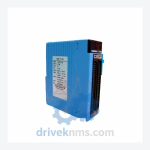
Yokogawa FA-M3 F3LC21-1N LC21-1N Multi-Link Communication Module
Yokogawa F3LC21-1N LC21-1N is listed for Communication Modules RFQ review. Confirm quantity, condition and destination before quotation.
RFQ-ready industrial model
Model: ALE111-S51 S1
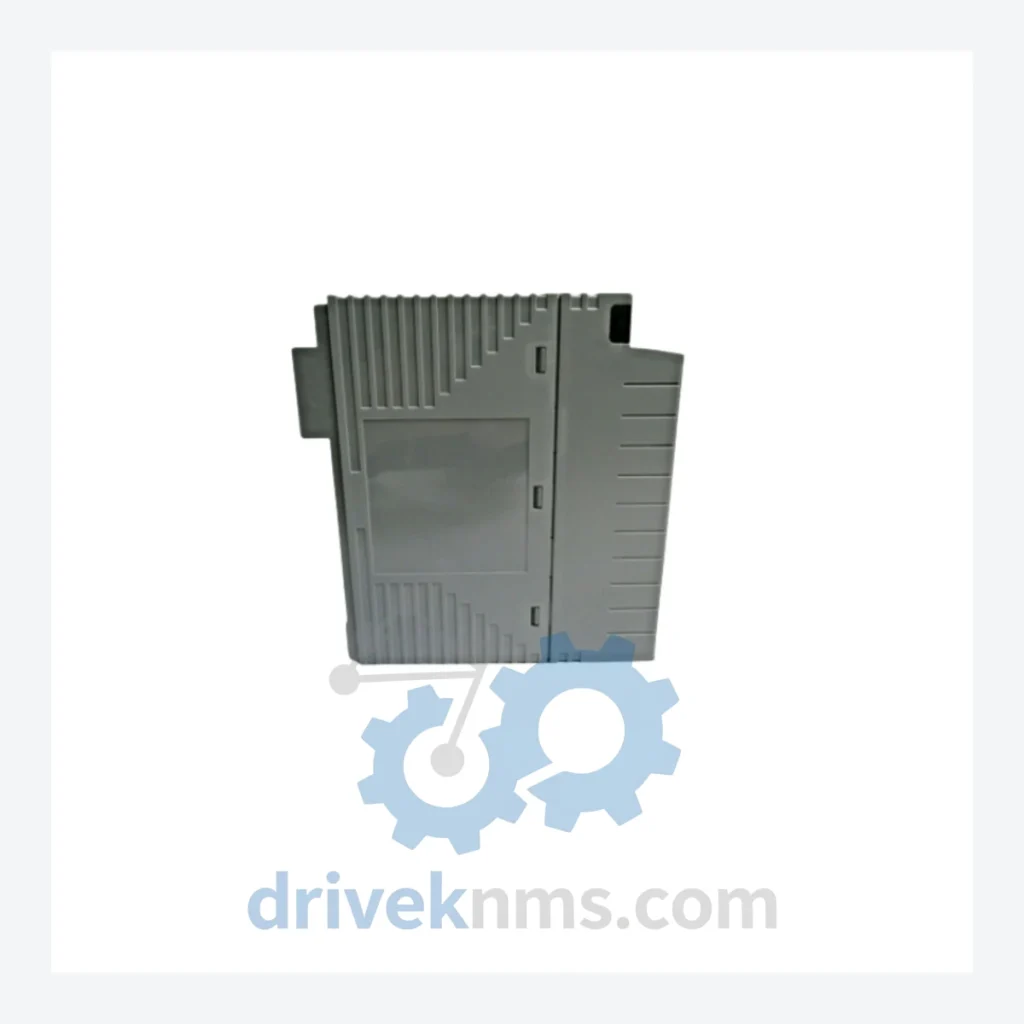
Product Overview
Commercial availability is handled through direct RFQ, model verification and export-oriented follow-up rather than public cart checkout.
Datasheet Preview
Use attached product manuals when available. If the manual is not public yet, request the full file directly through RFQ.
Commercial Path
Product pages on DRIVEKNMS are designed to verify model, brand and series first, then move the buyer into one clean quotation path.
Technical Dossier
The Yokogawa ALE111 series represents the Ethernet communication module family within the STARDOM FCN/FCJ autonomous controller platform. STARDOM (Scalable, Tiered, Autonomous, Real-time, Distributed, Open, Modular) is Yokogawa's field-level DCS/SCADA hybrid architecture, deployed extensively in oil & gas upstream facilities, chemical processing plants, LNG terminals, water treatment infrastructure, and nuclear auxiliary systems. The ALE111 module provides the primary Ethernet backbone interface for FCN-RTU and FCJ controller nodes, enabling FOUNDATION Fieldbus HSE, Modbus TCP, OPC DA/UA, and proprietary Vnet/IP communications. Its role as the network gateway module makes it a single-point-of-failure component in redundant STARDOM architectures, driving sustained demand for certified spare units across the global installed base.
The ALE111 module was introduced alongside the STARDOM FCN platform in the early 2000s as Yokogawa's response to the industry shift from proprietary fieldbus to open Ethernet-based control networks. Early hardware revisions (suffix S10, S20) supported 10/100BASE-TX with single-port topology and were designed for integration with Exaopc OPC server environments running on Windows NT/2000. The S30 and S40 revisions introduced dual-port Ethernet with ring redundancy support (Ethernet Ring Protection Switching, ERPS), aligning with IEC 62439-2 requirements for high-availability process networks. The S51 revision — as in the ALE111-S51 S1 — represents the current production-mature hardware generation, incorporating enhanced EMI shielding, extended operating temperature tolerance (−20°C to +60°C), and firmware compatibility with STARDOM R10.x and later software releases. The S1 suffix denotes the standard single-module configuration without factory-installed redundancy option. Compatibility between hardware revisions requires attention: S10/S20 modules are not firmware-compatible with FCN controllers running R8.x or later without a full node upgrade. S30 and above maintain backward compatibility within the same FCN chassis generation.
The following SKUs represent the verified ALE111 series module range within the Yokogawa STARDOM FCN/FCJ platform. Modules are classified by function:
Ethernet Communication Modules (ALE — Advanced Logic Engine Ethernet)
ALE111-S51 S1: Single-slot Ethernet comm module, 100BASE-TX, STARDOM FCN R10.x compatible, standard configuration.
ALE111-S51 S2: Dual-redundant Ethernet comm module, ring topology support, ERPS-compliant, FCN R10.x.
ALE111-S40 S1: Ethernet comm module, dual-port, FCN R8.x/R9.x compatible, ERPS ring support.
ALE111-S40 S2: Redundant pair configuration, dual-port Ethernet, FCN R8.x/R9.x, ring topology.
ALE111-S30 S1: Ethernet comm module, dual-port 100BASE-TX, FCN R6.x–R8.x compatible.
ALE111-S20 S1: Single-port 10/100BASE-TX, FCN R4.x–R6.x, legacy OPC DA integration.
ALE111-S10 S1: Original production revision, single-port Ethernet, FCN R2.x–R4.x, end-of-life hardware.
CPU / Controller Modules (ACF — Autonomous Control Function)
ACF11S-S10 S1: FCN-RTU CPU module, 32MB application memory, IEC 61131-3 function block execution.
ACF11S-S20 S1: Enhanced FCN CPU, 64MB memory, extended I/O scan rate, STARDOM R6.x+.
ACF11S-S30 S1: Current-generation FCN CPU, 128MB, dual Ethernet port, R10.x compatible.
Digital Input Modules (ADV — Analog/Digital I/O)
ADV151-P50 S1: 16-channel 24VDC digital input, sink type, IEC 61131-2 compliant.
ADV161-P50 S1: 32-channel 24VDC digital input, high-density, FCN I/O bus compatible.
Digital Output Modules
ADV551-P50 S1: 16-channel 24VDC digital output, source type, 0.5A per channel.
ADV561-P50 S1: 32-channel 24VDC digital output, high-density, FCN I/O bus.
Analog Input Modules
AAI141-S03 S1: 16-channel 4–20mA analog input, 16-bit resolution, HART pass-through.
AAI841-S03 S1: 8-channel thermocouple/RTD universal analog input, FCN compatible.
Power Supply Modules
APS10S-S10 S1: FCN base unit power supply, 24VDC input, 30W output, DIN rail mount.
APS10D-S10 S1: Redundant power supply module for FCN chassis, dual-feed configuration.
ALE111 modules present specific test challenges due to their role as the active Ethernet interface on the FCN backplane bus. DriveKNMS applies a structured test protocol for each unit processed:
1. Backplane bus continuity verification: Each module is seated in a compatible FCN test chassis and bus communication integrity is confirmed at the hardware register level before firmware loading.
2. Ethernet port functional test: Both physical ports (where applicable) are tested for 10/100BASE-TX autonegotiation, frame transmission integrity, and VLAN tagging behavior using a calibrated network analyzer.
3. Firmware revision identification: Onboard firmware version is read and logged. Modules are matched to customer-specified FCN software revision requirements before dispatch.
4. Thermal cycle screening: Units are subjected to a 4-hour thermal cycle (0°C to 55°C) to screen for latent solder joint failures common in aged communication modules.
5. EMI susceptibility check: Conducted emissions are measured at the Ethernet port to confirm compliance with IEC 61000-4-4 (EFT) and IEC 61000-4-5 (surge) immunity thresholds relevant to industrial panel environments.
Continue The Model Path
Move from this exact model into the matching system hub, brand archive, model-family archive or lifecycle sourcing route before sending a final RFQ list.
Related Paths
Yokogawa F3LC21-1N LC21-1N is listed for Communication Modules RFQ review. Confirm quantity, condition and destination before quotation.
Yokogawa F3RZ81-OF is listed for STARDOM RFQ review. Confirm quantity, condition and destination before quotation.
Yokogawa ALP111-S00 S1 is listed for STARDOM RFQ review. Confirm quantity, condition and destination before quotation.