
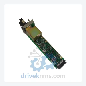
YOKOGAWA AIP512 RIO Bus Connection Module – CENTUM Series
Yokogawa AIP512 is listed for CENTUM Series RFQ review. Confirm quantity, condition and destination before quotation.
RFQ-ready industrial model
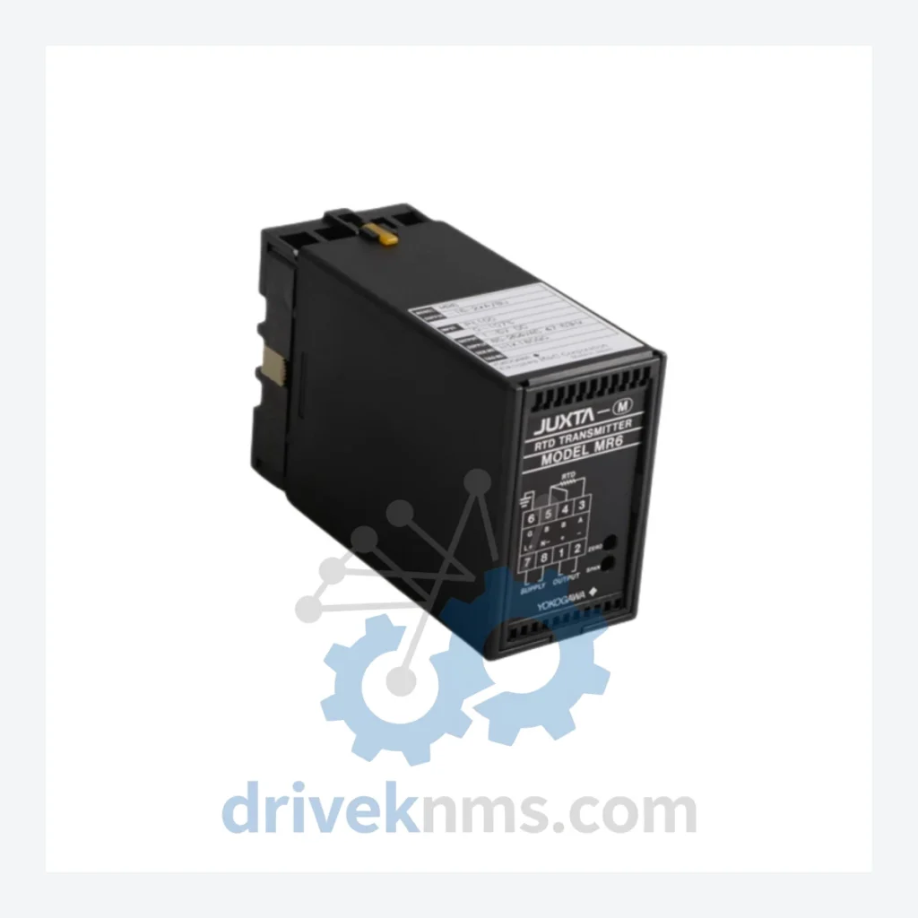
Model: Yokogawa MR6 MR6-16-2*A/BU
Product Overview
Commercial availability is handled through direct RFQ, model verification and export-oriented follow-up rather than public cart checkout.
Datasheet Preview
Use attached product manuals when available. If the manual is not public yet, request the full file directly through RFQ.
Commercial Path
Product pages on DRIVEKNMS are designed to verify model, brand and series first, then move the buyer into one clean quotation path.
Technical Dossier
The MR6 series was developed as part of Yokogawa's broader data acquisition strategy, bridging the gap between standalone chart recorders and fully networked DCS environments. Early MR6 configurations focused on analog signal acquisition — primarily RTD (Pt100, Pt1000, JPt100) and thermocouple inputs — with local display and serial communication output.
As industrial networks evolved, later MR6 variants incorporated Ethernet-based communication options and expanded compatibility with Yokogawa's SMARTDAC+ GA10 data logging software. The architecture uses a modular backplane design, allowing channel expansion without full system replacement — a key factor in its longevity across multi-decade plant lifecycles.
Compatibility considerations are significant: early MR6 firmware versions may not support modern Modbus TCP implementations without gateway adapters. Engineers integrating MR6 modules into contemporary SCADA environments should verify firmware revision levels and communication card compatibility before deployment. Yokogawa's transition toward the GP10/GP20 and GX10/GX20 SMARTDAC+ recorders represents the functional successor path for new installations, but does not provide direct plug-in replacement for existing MR6 backplane slots.
The following SKUs represent verified models within the Yokogawa MR6 series, classified by functional category. Each model is documented based on its primary signal processing role within a data acquisition architecture.
RTD / Resistance Input Modules
Thermocouple / mV Input Modules
DC Voltage / Current Input Modules
Communication & Interface Modules
Power Supply & Mainframe Units
DriveKNMS maintains a dedicated sourcing network for obsolete Yokogawa instrumentation, including the MR6 series. Our procurement approach covers:
Q: How are RFQ terms confirmed?
A: Quantity, required condition, documentation needs, destination and sourcing route are confirmed during RFQ review before quotation.
MR6 modules present specific quality verification challenges due to their backplane communication architecture and multi-channel analog front-end design. Standard visual inspection is insufficient to confirm functional integrity — particularly for RTD input modules where channel-to-channel isolation and measurement accuracy must be verified under load.
DriveKNMS applies the following test protocol to all MR6 modules prior to shipment:
Q: How is condition confirmed before quotation?
A: Available condition, photos, test records and documentation are checked according to the requested model and sourcing channel before a formal RFQ response.
Continue The Model Path
Move from this exact model into the matching system hub, brand archive, model-family archive or lifecycle sourcing route before sending a final RFQ list.
Related Paths
Yokogawa AIP512 is listed for CENTUM Series RFQ review. Confirm quantity, condition and destination before quotation.
Yokogawa KS1*B is listed for DCS Cards RFQ review. Confirm quantity, condition and destination before quotation.
Yokogawa SR1B-045N-1KC is listed for CENTUM Series RFQ review. Confirm quantity, condition and destination before quotation.