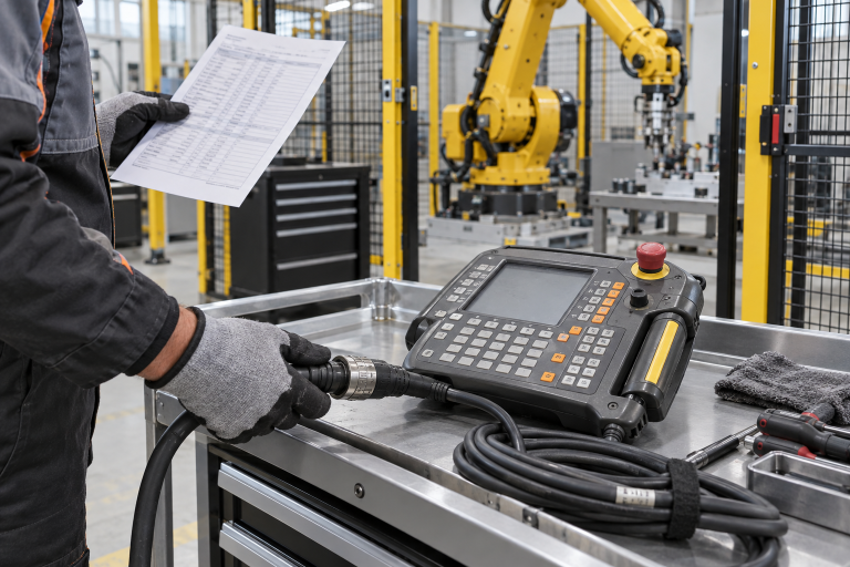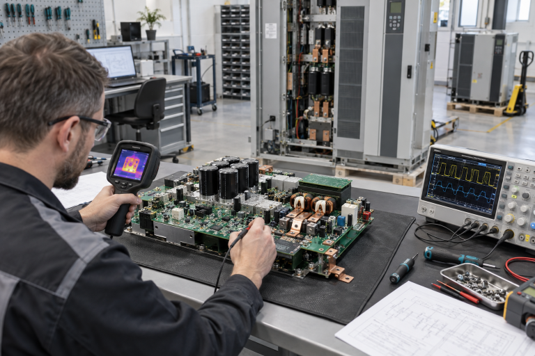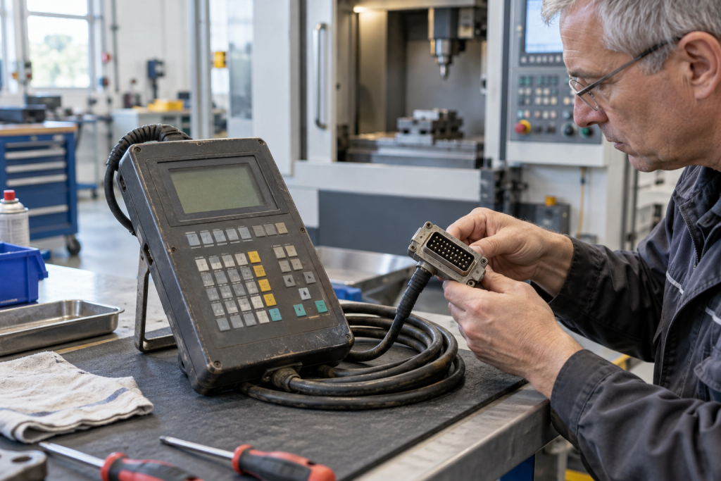
A machine-tool operator panel is often blamed when an axis cannot be jogged, a screen becomes intermittent, or a key press appears to be ignored. But the panel is only one part of the operator path. A damaged cable, loose connector, controller interface, machine mode, enabling device or safety condition can produce a similar symptom. Ordering a replacement based on appearance alone risks receiving a unit with a different execution or interface. For an older Indramat installation, begin by documenting the BTV06.1 label and the connected control architecture before disturbing the machine.
Capture the hardware identity before testing
Photograph the full rear and front labels, connector arrangement, cable ends, any adapter or junction box, and the controller or CNC identifier. Record the exact BTV model and suffix, not just “BTV06.” Note whether the display is blank, backlight-only, frozen, or readable; whether keys fail consistently or only after cable movement; and whether the panel is recognized at startup. The site’s original electrical drawings, machine build sheet and previous replacement records may identify interface versions that are not obvious from the front bezel.
Preserve fault text, status indicators and the machine state at the time of failure. Ask whether the issue started after cleaning, a collision, panel relocation, cable routing work, coolant exposure or a controller restart. Those details help distinguish physical damage from a communication or configuration issue. Avoid repeatedly power-cycling an unstable unit before the controller messages and any available event history are recorded.
Divide the operator path into testable segments
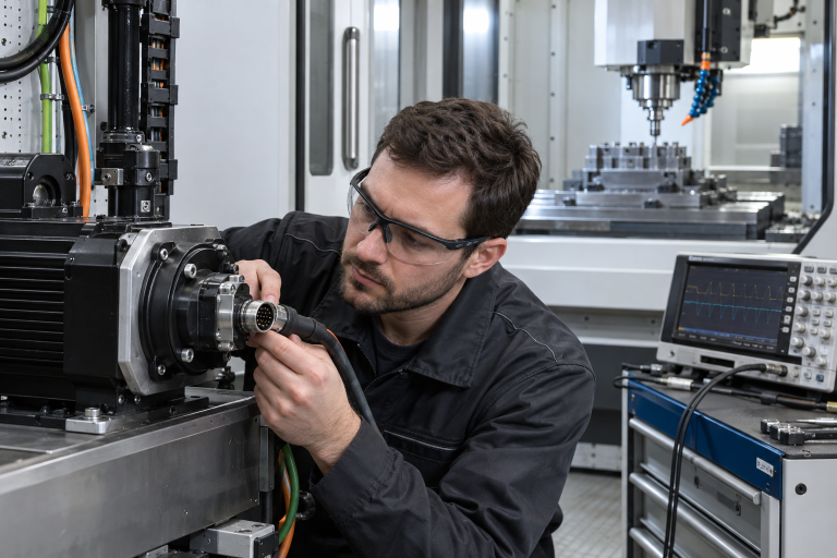
Trace the path from panel electronics through the connector and cable to the machine control. Check visible strain relief, bends, abrasion, contamination and connector retention while following the manufacturer and site procedures. If a symptom changes when the cable is moved, document exactly where and under what safe, de-energized or approved test condition it changes. Do not flex connectors on a live machine to provoke a fault. Inspect the controller-side connection and any intermediate junction hardware without assuming that a clean exterior proves electrical continuity.
Separate the user-interface issue from motion permission. Confirm the selected mode, enable conditions, emergency-stop state, machine interlocks and relevant controller alarms using approved diagnostics. A panel that displays normally can still be blocked from enabling motion by a safety chain or machine condition. Conversely, a display or key fault may coexist with an unrelated axis drive alarm. Keep the evidence from these paths separate in the work order rather than combining every symptom into “pendant failure.”
Check the control generation and configuration
Older machine tools may have accumulated replacement panels, cable extensions or controller upgrades over decades. Compare the installed interface and connector pinout with the original machine documentation and any retrofit records. Confirm the control family, panel execution, cable type and software generation. Do not assume two BTV units are interchangeable because the housings or key layouts match. Differences in communication interface, firmware, memory or machine configuration can matter even where the panel appears physically compatible. For a related operator-terminal case, DriveKNMS also has a Pro-face GP4000 panel replacement and project-backup guide; its hardware is different, but the need to verify the full terminal and controller configuration is similar.
Back up the CNC or machine project using the authorized method before replacing an operator component. Retain application data, machine parameters, offsets and any panel-specific settings required by the service procedure. A panel exchange should not become an occasion to alter machine parameters without approval. If a known-good cable or spare is used as a diagnostic substitution, mark it clearly and restore the approved configuration after the test.
Use the catalog entry as an identification lead
DriveKNMS lists an Indramat BTV06.1HN-RS-FW operator panel. Treat that as a part reference to compare against the installed unit, not a blanket compatibility statement. Match every character of the type code and inspect connector style, keys, display, rear label and revision. If the installed suffix differs, document the difference and have the machine controls specialist verify the interface and application requirements before ordering.
When asking for a quotation, state the condition required and provide photographs in focus, including a ruler or reference where physical dimensions are relevant. Include the connected controller, cable part number, fault behavior and machine type. Ask what inspection or functional test evidence is available. Availability, repairability and test scope should be confirmed rather than assumed from a web listing.
Plan replacement without losing machine evidence
Schedule work with production and maintenance so the machine is in an approved safe state. Follow lockout, electrical and machine-specific instructions; preserve the original unit until the replacement has been accepted. Record the as-found connections before removal and label each lead. After installation, confirm the correct panel recognition, display and keypad response, mode selection, enabling device, emergency-stop path and machine status in the manufacturer’s specified sequence. Test controlled functions at the authorized stage and verify that all temporary diagnostic components have been removed.
Close the job with as-left photos, exact installed part code, controller version, parameter backup reference and results of each acceptance step. If the fault remains, stop treating the panel as the only suspect and return to the evidence: cable, connector, controller interface, configuration and safety permissions. This method prevents repeated part swaps and creates a useful baseline for the next failure on a legacy machine.
Questions maintenance teams ask
Does a blank BTV06.1 display prove the panel has failed?
No. Verify the approved supply and connection path, controller status and any intermediate hardware. Capture the exact behavior before replacing a unit.
Can I replace a BTV06.1 with any panel that has the same housing?
No. Match the full suffix, interface, connector, control generation and machine configuration. Appearance alone is not a compatibility test.
What should I send with an operator-panel RFQ?
Send clear front and rear labels, connector and cable photos, the machine and controller identifiers, symptom chronology, required condition and target outage date.
Why does the panel work while machine motion stays inhibited?
Motion permission can depend on mode, enable switch, emergency-stop and machine interlocks. Review those signals through the approved safety and CNC diagnostics instead of assuming a panel fault.
For a BTV06.1 inquiry, send DriveKNMS the complete type code, connector and cable photographs, controller family, fault evidence and machine shutdown window. We can help check the catalog identity and sourcing documentation before your team approves a replacement.
© 2026 DriveKNMS. All rights reserved. Official Website: https://driveknms.com Inquiry: sale@driveknms.com | WhatsApp/Tel: +86 18359293191