A drive that trips on overvoltage, undervoltage, precharge or power-stage faults can trigger an immediate request for a replacement power board. Yet the board may be reacting correctly to a supply dip, failed precharge path, braking issue, motor-side fault or abnormal load. If the causal condition remains, installing another board can turn one repair into two failures and leave the machine unavailable.
Treat the drive as an energy-conversion chain rather than a single circuit board. On a Danfoss FC installation, the product label and drive configuration identify the hardware family, but diagnosis still begins with the incoming supply, DC link, switching stage, motor and application. Safe isolation and discharge times are essential: a VFD DC bus can retain lethal energy after input power is removed.
Preserve the fault before resetting
Record the exact alarm code, timestamp, speed and torque demand, process state, line voltage, recent starts, ambient temperature, cooling condition, and whether the trip occurred during acceleration, deceleration or steady operation. Save the drive event log and parameter set before clearing faults. An alarm family is a clue, not a final diagnosis; successive events can reveal whether the supply or load changed before the power stage reported a fault.
Photograph the complete drive nameplate, control and power-board labels, option cards, terminal connections, braking resistor, motor data, and cable routing. Note frame size, voltage class, current rating, firmware, fieldbus, safety options and parameter checksum where available. A shortened board number without the drive’s complete identity makes both the quotation and a later repair difficult to validate.
Check the input and precharge path
After applying the site isolation procedure and proving absence of voltage, inspect input fuses, contactors, line reactors, terminals and signs of heat or tracking. Qualified staff can compare phase-to-phase supply measurements at the appropriate test points and review whether imbalance or sag coincides with the event. Do not make live measurements unless the risk assessment, instrument category, PPE and work authorization specifically permit them.
Precharge limits the inrush used to charge the DC link. Check the specified charging path, resistor or circuit, contactors, feedback and timing against the manufacturer procedure. A failed precharge component can stress capacitors and power electronics, while a damaged board may be a symptom rather than the first fault. Capture the measured result, test setup and service manual reference rather than writing only “precharge OK.”
Understand what the DC bus is telling you
Compare the DC-bus reading with the expected range for the actual AC input and drive topology. Review ripple, phase consistency, discharge behavior and the point at which the value becomes abnormal. Capacitor bulging, leakage, discoloration, odor or unusual temperature are inspection findings, not a substitute for a qualified electrical test. Never probe an energized bus using an improvised procedure or bypass the discharge circuit to save time.
During deceleration, a rising bus can reflect regenerative energy and an incorrectly sized, disconnected or thermally protected braking path. During steady operation, recurring bus dips can indicate a weak upstream supply or poor connection. Relate every measurement to load, speed, line condition and event time. A snapshot without operating context can send procurement toward an unnecessary board replacement.
Separate control electronics from the power stage
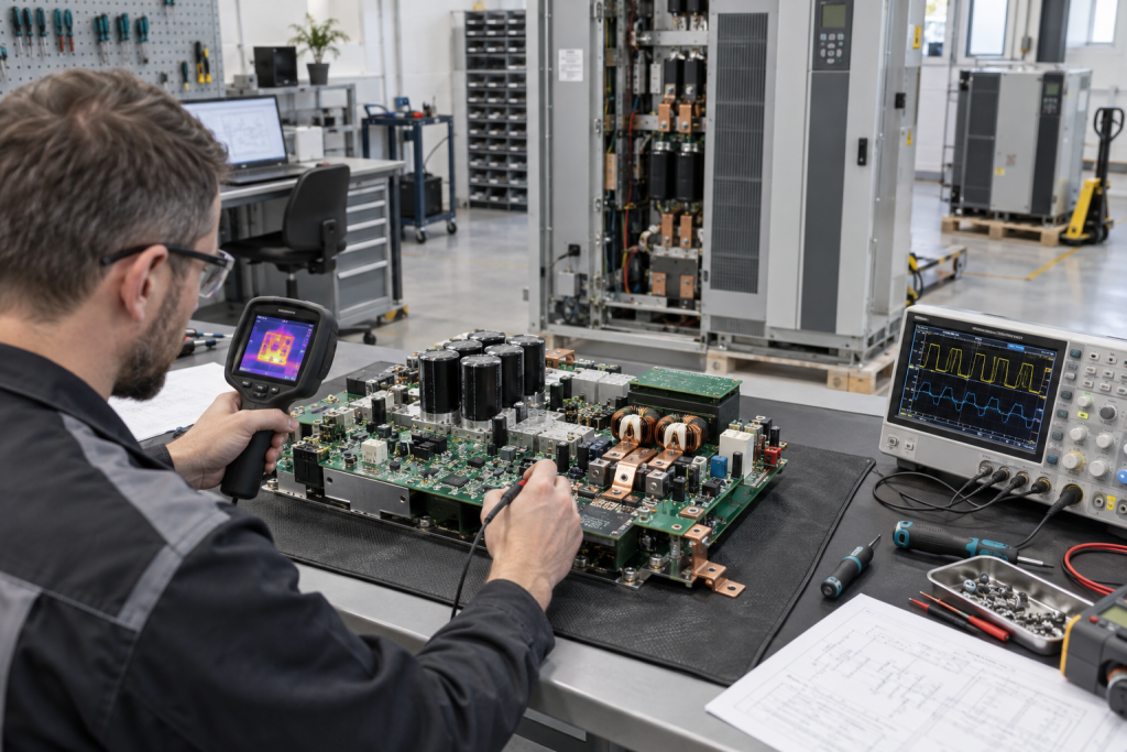
The Danfoss 175H3828 DT5 / 175H7068 power board is useful as an exact catalog reference, but confirm the full drive model, board revision, connectors, rating, firmware relationship and tested condition before purchase. Check gate-drive wiring, DC-bus sensing, cooling path, connector pins and contamination. If control signals are absent or inconsistent, compare the control board and power board interfaces before assuming the power board alone is defective.
A Danfoss 175H4669 DT3 control board has a different role. Keep the control and power assemblies distinct in the fault tree, material list and receiving inspection. If a repair supplier offers a substitute or exchange unit, require written identification of what was tested and the exact serial or revision that will ship.
Test the motor and application before restart
Inspect motor insulation, cable condition, output connections, bearings, driven load, coupling and ventilation according to the approved maintenance method. A ground fault, phase imbalance, jammed mechanism, excessive inertia or repeated starts can stress the drive. Where the application permits, separate motor and drive checks under controlled conditions, never by defeating interlocks or operating outside the documented procedure.
After replacement, confirm parameters against the approved backup, verify motor nameplate data and feedback/options, and test at defined low-risk operating points. Observe current, bus behavior, temperature, speed feedback, torque and fault history. Agree on a stop criterion with operations. The result should show that the initiating condition is corrected, not merely that the drive powers up without an alarm for a few minutes.
Questions Maintenance Teams Ask
Can an overvoltage trip confirm a bad power board?
No. Regenerated energy, braking path problems, supply events, settings and sensing issues can create the same alarm. Correlate the bus trend with speed and load.
How long should I wait before checking a VFD DC bus?
Follow the exact manufacturer discharge time and verify absence of voltage with an appropriately rated meter using the site-approved procedure. Do not rely on an indicator lamp.
What details belong in a power-board RFQ?
Provide full drive and board numbers, revision, voltage/current rating, frame, firmware/options, fault history, photographs, quantity, condition and required test evidence.
Should the replacement be tested only on a bench?
Bench evidence is useful, but final acceptance should include the installed supply, motor, braking path, load profile, parameters and a controlled functional test.
Send DriveKNMS the complete Danfoss drive and board labels, DC-bus and fault history, input and motor ratings, option-card photos, acceptable condition, and required delivery date. We can help make the sourcing request specific enough to avoid a mismatched board.
© 2026 DriveKNMS. All rights reserved. Official Website: https://driveknms.com Inquiry: sale@driveknms.com | WhatsApp/Tel: +86 18359293191